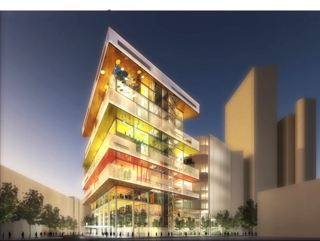
Credit ROGERS STIRK HARBOUR + PARTNERS
Long hospital corridors: disorientating, oppressive, intimidating. It is a journey that cancer patients are familiar with – traipsing along endless passageways between consultants’ rooms, chemotherapy wards and radiotherapy departments. The latter are particularly depressing, involving descents into remote basements illuminated by harsh artificial light.
The days of navigating endless corridors will be a thing of the past at the new £160m Cancer Centre at Guy’s and St Thomas’ Hospital, which opens in autumn 2016.
Lead architect Rogers Stirk Harbour + Partners has reduced the distances between departments on the 200,000ft2 site by grouping the functions of the building into manageable, multi-storey sections – termed ‘villages’ by the hospital. This means consulting rooms and treatment departments are close together.
The radiotherapy ‘bunkers’ – typically found at basement level – have been moved to the second floor, where patients can benefit from daylight while they await their treatment.
The heavy radiation shielding on these rooms has required a massive reorganisation of the services and clever structural design, including ducting on the outside of the building to maximise internal space.
Project Team
Client: Guy’s and Thomas’ NHS Foundation Trust
Build project manager: Essentia
Main contractor: Laing O’Rourke
Architects: Rogers Stirk Harbour + Partners and Stantec
Structural and building services engineers: Arup
Academic partner: King’s College London
Designing at a human scale
The radiotherapy department is vertically stacked over three levels, each of which corresponds to a particular stage of a patient’s treatment. The radiotherapy machines – known as linear accelerators (Linac) – and reception are on the second floor, the staff areas on the third, and treatment-planning and imaging equipment (CT and MRI scanners) on the fourth.
The floors are organised into high-technology – or ‘science of treatment’ – zones towards the rear of the building, and low-technology, or ‘art of care’, zones towards the front of the cancer centre.
A range of services that are currently delivered separately will be brought together in the chemotherapy unit, which means different patient groups and treatment sessions can be run concurrently. The unit also includes a research floor for King’s College London university, potentially giving more patients the opportunity to take part in clinical trials.
The outpatients department encompasses elements that outpatients are most likely to use – such as imaging and minor procedures facilities – thus allowing them to remain in one place during their visit.
In all, the hospital’s new cancer centre will include six radiotherapy bunkers, a 44-chair chemotherapy day unit, 22 consulting rooms, and support services. A whole floor has also been set aside for research facilities and laboratories.
Rooms with a view
The cancer centre will be the first such development in the UK – and one of the first in Europe – to site radiotherapy treatment facilities above ground level. Linac machines are typically housed in basements because the ground can be used as part of the radiation shielding for the department.
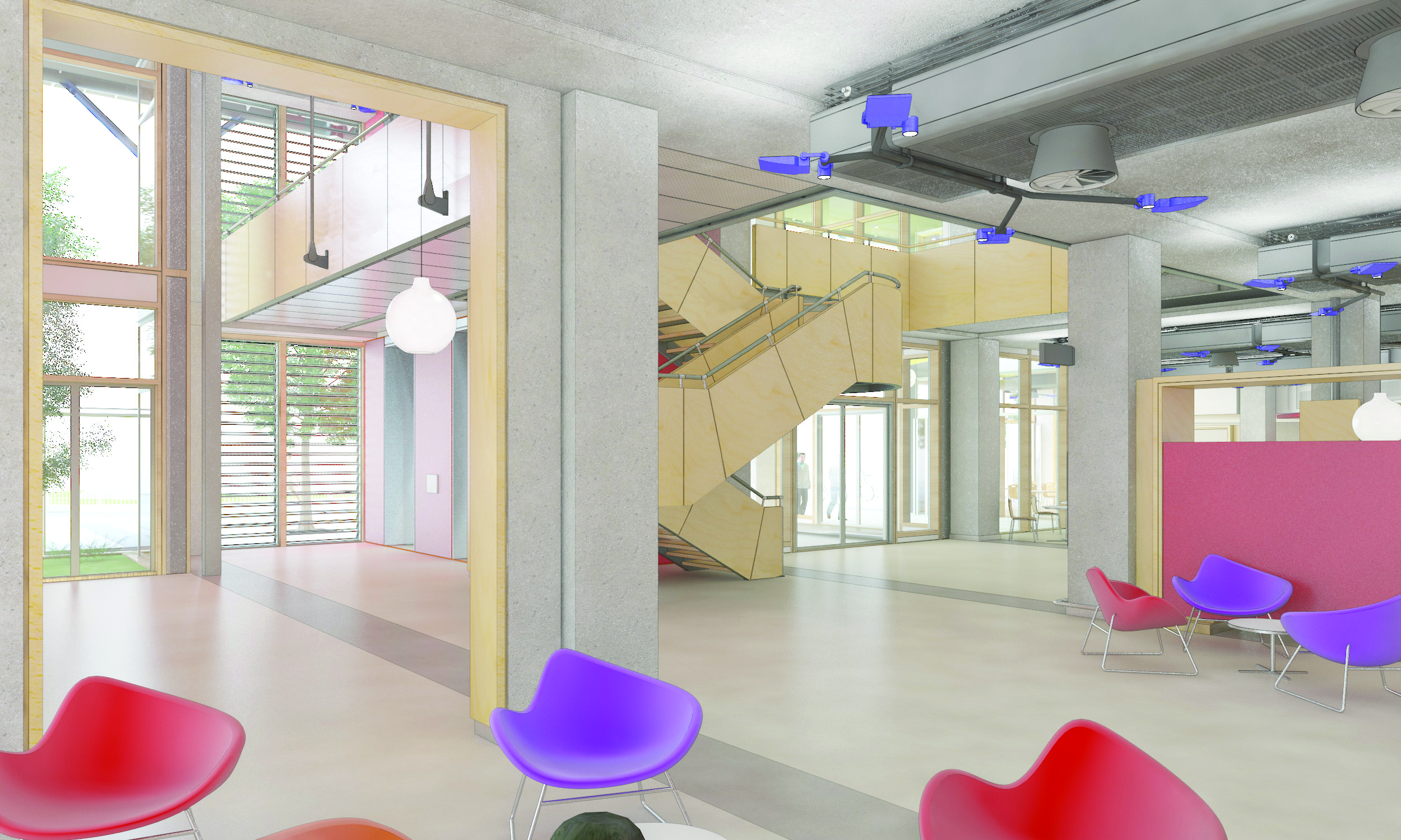
An artists impression of one of the naturally ventilated and light-filled atria
Credit ROGERS STIRK HARBOUR + PARTNERS
Malcolm Turpin, associate director at structural and building services engineers Arup, says: ‘We wanted to avoid patients having to go to the basement for treatment, and maximise daylighting, while controlling heat gains with a well-shaded façade.’
In order to locate the Linacs in the smallest possible footprint, the depth of the new radiotherapy department’s walls was reduced from the traditional 3m-thick concrete structures to half the thickness, using high-density concrete with 819mm lead blocks for shielding. These blocks can be dismantled, so the area could be redesigned in the future if less-invasive cancer treatment became available and Linac procedures were no longer required. Patients will enter the bunkers directly, through heavily lead-shielded doors, rather than via a long concrete maze.
To accommodate all the equipment and shielding, the radiotherapy level needed to be at least 6m high. This meant inserting plant zones with reduced ceiling heights immediately below and above the Linac floor.
Turpin says: ‘This was a groundbreaking design that took a lot of integrated engineering work, and which is an exciting development for the future delivery of cancer treatment.’
Ventilation strategy
The ventilation requirements of the building vary according to the use of the space, says Turpin. Some spaces require high air change rates and filtration to ensure clean air, while others have lower demand.
Typically, rooms will be mechanically ventilated, except for the consulting and exam rooms, which are on the perimeter of the floorplate and are naturally ventilated through an opening panel in the façade.
The ventilation strategy needed to deliver occupant comfort and infection control, while remaining low energy and flexible for the future, adds Turpin.
Floor-by-floor ventilation distribution with air handling units (AHUs) – located in a plant tower to the north of the building – are central to overcoming the design challenges presented by the building’s height and the diversity of room types.
This keeps the ventilation on each level separate and adaptable for future needs, while adjacent floors remain fully functional. It also helps to minimise the number of services risers, freeing up space in the building, and reducing the length of ductwork runs – which, in turn, helps to minimise system pressure drops and, therefore, energy consumption.
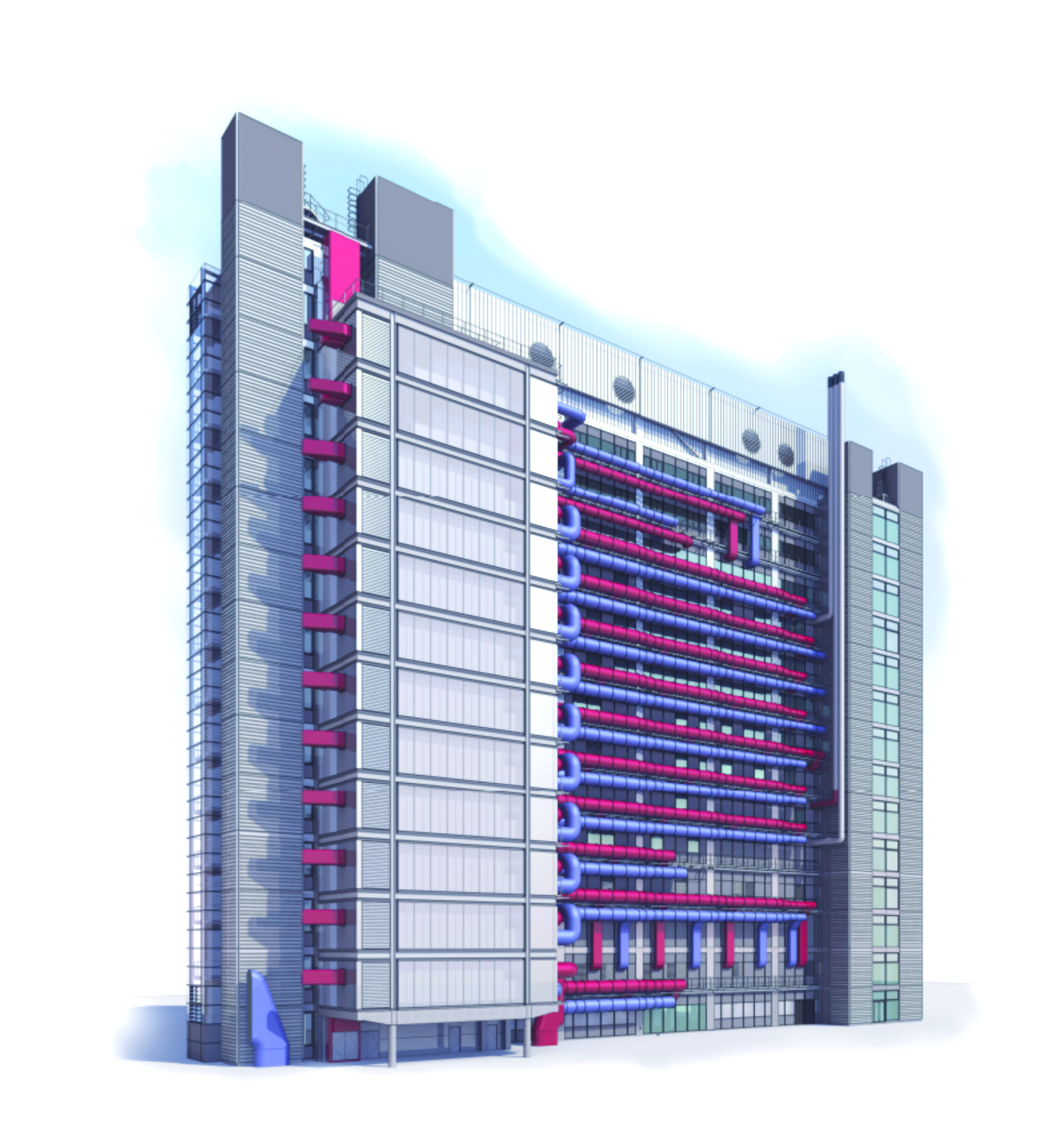
The 12 storey plant tower juts out from the northern façade where external ducts are also visible
Credit ROGERS STIRK HARBOUR + PARTNERS
To avoid large horizontal ductwork runs inside the building – which are often associated with floor-by-floor ventilation strategies – the primary ventilation distribution is outside the building. This complements Rogers Stirk Harbour + Partners’ architectural vision of expressing the high-tech ‘science of treatment’, says Turpin.
The most highly ventilated clinical spaces are to the north of the building, as part of the ‘science of treatment’ zone. This is close to the external ductwork, which helps to minimise large duct runs deep into the building, easing congestion and boosting ceiling height by 2ft.
The ventilation systems in the ‘art of care’ zone, to the south of the building, were kept to a minimum, says Turpin, with natural ventilation used wherever possible, particularly in perimeter consult/exam spaces and the atria. This helped to minimise energy consumption and maximise the amount of natural daylight entering the building.
Ventilation systems for specialist treatment have to meet air change and filtration rates to maintain the required degree of cleanliness. The ventilation system for the Linac bunkers is a variable air volume (VAV) system with local temperature control to each bunker.
The VAV system allows the air volume for each bunker to be altered from the bunker control rooms and set back when unused. The air volume required depends on the treatment cycle, and a boost function can be used in one bunker at a time to purge contaminated air generated during the most intensive treatment cycles.
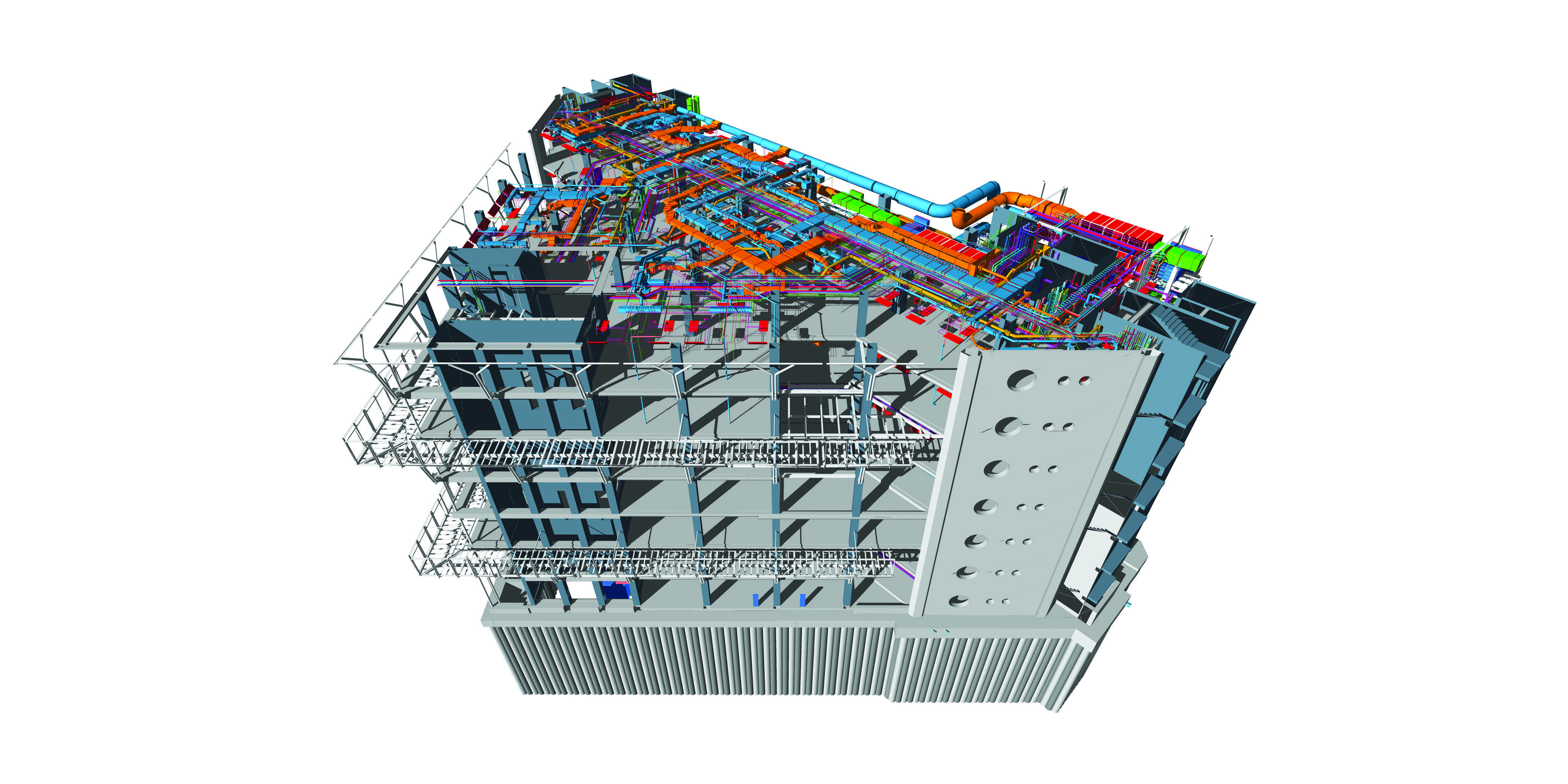
BIM image of a portion of the services overlaid with the building structure
CREDIT ARUP
Heating and cooling
The cancer centre has an array of room types, ranging from specialist imaging rooms – requiring accurate temperature control – and equipment and server rooms with high heat-load densities, to three-storey atria and consultation/exam rooms.
Turpin says the heating and cooling terminal units are selected to suit the different requirements of these spaces, and include duct-mounted heating coils, radiant panels, underfloor heating, fan coil units and chilled beams.
‘The aspiration with all these solutions was to minimise energy and provide appropriate levels of comfort,’ says Turpin.
Chilled water for HVAC systems is generated from highly efficient and responsive Turbocor chillers, and the Linac cooling is provided by free-cooling chillers, which have a consistent year-round cooling load.
Heating is provided from a site-wide heating network, which includes a combined heat and power system.
The space heating and cooling water systems are shared between floors, and can be isolated floor by floor as necessary, Turpin adds.
The offsite solution
Located in busy London Bridge, the cancer centre’s footprint reaches to the edges of its triangular site. As a result, layout and storage space were at a premium, making construction a logistical challenge.
To overcome this, main contractor Laing O’Rourke used its design for manufacture and assembly (DfMA) processes to make parts in a factory for on-site assembly, thereby reducing in-situ building work.
The Guy’s and St Thomas’ Hospital’s new cancer centre is targeted to achieve the BREEAM Healthcare Excellence rating, and aims to accommodate 700 outpatients at peak times.
People were at the heart of the design, and patient feedback inspired the project team to come up with a novel solution that brought the radiotherapy units into the light and out of the basement – which was also restricted because of a Roman boat buried 4m below the site!