
Sponsors: Condair and Konvekta
For an alternative way to access this module, CIBSE member, Jos Brownlie provides a video reading the module: Module 264 recording
The decarbonisation of building services is increasingly constrained not by a lack of ambition but by the renewed application of well-established techniques. Nowhere is this more evident than in cooling. Vapour compression systems have undergone decades of optimisation and, while incremental efficiency gains remain possible, the fundamental thermodynamic cycle is mature.
At the same time, the regulatory and environmental context continues to tighten, with increasing pressure to reduce operational energy consumption, phase down high global warming potential (GWP) refrigerants and move towards net zero carbon buildings. In this context, alternative cooling strategies that can materially reduce reliance on mechanical refrigeration are gaining renewed attention. One such approach is exhaust air evaporative cooling (EAEC), which combines well-established physical principles with modern air handling integration to deliver significant reductions in cooling energy demand.
Cooling by evaporation
The underlying mechanism of EAEC is simple, with the basic principles having been applied in various forms for several decades, and the thermodynamic benefit can be significant under favourable conditions. Evaporative cooling exploits the latent heat of vaporisation as water changes phase from liquid to vapour, absorbing a substantial quantity of energy from its surroundings. In an adiabatic process, this energy is drawn from the sensible heat of the air, reducing its dry-bulb temperature while increasing its moisture content.
The process approximately follows a line of constant enthalpy on the psychrometric chart, with sensible heat decreasing and latent heat increasing by an equivalent amount. In conventional direct evaporative cooling, this results in a simultaneous reduction in air temperature and increase in moisture content, with the theoretical limit defined by the wet-bulb temperature of the air – CIBSE Journal CPD Module 109: Evaporative cooling for building environmental systems considers the evaporative cooling process in more detail.
For building applications, this moisture addition is often a critical constraint. Internal environmental conditions must remain within acceptable humidity limits to ensure occupant comfort, prevent condensation and avoid degradation of building fabric or process environments.
As a result, direct evaporative cooling is typically limited in its application, particularly in climates where ambient humidity is already elevated. Since the process relies on the properties of outdoor air, its effectiveness varies significantly with weather conditions, performing best in hot, dry climates and poorly in hot, humid ones.
Working beyond ambient wet-bulb constraints
Exhaust air evaporative cooling addresses both of these limitations by relocating the evaporative process from the supply airstream to the extract airstream. In a typical configuration, return air from the conditioned space is passed through an adiabatic humidifier, where it is cooled through evaporation and approaches saturation.
This cooled exhaust air is then used as a heat sink within an air-to-air heat exchanger or run-around coil, transferring heat from the incoming fresh air without any direct mixing of the two airstreams. The extracted air, now both cooler and more humid, is discharged to the atmosphere, while the supply air is sensibly cooled before entering the occupied space. Because the evaporative process is confined to the exhaust side, no additional moisture is introduced into the building, allowing the system to operate at maximum evaporative capacity without compromising internal conditions.
This seemingly modest rearrangement has significant thermodynamic implications. By introducing evaporative cooling on the exhaust side, the extract air temperature can be significantly reduced, increasing the temperature differential across the heat exchanger. This enhances the driving force for heat transfer and allows the heat recovery device to operate as a cooling component during warm conditions. In practical terms, supply air temperatures can be reduced by 10K1 or more under favourable conditions, using primarily the energy required to move air and circulate water, although this must be balanced against increased air-side pressure drop and associated fan power.
A further advantage arises from the choice of working fluid. Whereas conventional indirect evaporative cooling systems rely on ambient air as the secondary airstream, EAEC systems use indoor extract air. In many mechanically-conditioned buildings, this air is maintained within a relatively controlled range of temperature and humidity, although actual conditions will vary significantly with occupancy, internal gains and application.
The use of extract air moderates the influence of ambient humidity, providing more stable performance than systems relying directly on outdoor air. However, the process remains fundamentally bounded by wet-bulb conditions and effectiveness still varies with operating conditions.
In thermodynamic terms, the limiting wet-bulb temperature becomes that of the extract air rather than the ambient air, partially mitigating one of the principal constraints on evaporative cooling.
System architecture
The performance of an EAEC system is strongly influenced by the design of the heat exchanger and the configuration of airflow paths. Plate heat exchangers are the most widely used solution, offering a compact and reliable means of transferring heat between adjacent air streams. In contrast, closed-loop run-around coil systems decouple supply and exhaust AHUs entirely, enabling separate plantrooms, retrofit installations and integration with additional hydraulic components such as heat pumps – capabilities not achievable with plate exchangers.
Cross-flow arrangements are common in packaged air handling units owing to their simplicity and ease of manufacture, although counter-flow configurations can achieve higher effectiveness where geometry permits.2 In both cases, the exchanger typically incorporates alternating dry and wet channels, with the exhaust air passing through wetted passages and the supply air through dry ones. The effectiveness of heat transfer depends on factors including surface area, airflow velocity, and the uniformity of water distribution on the wet side.3
Where physical separation of supply and exhaust ducts is required, run-around coil systems, which are effectively a counter-flow heat exchanger, provide an alternative. These systems use a pumped liquid loop – typically water with glycol – to transfer heat between coils located in separate airstreams. While the dual heat transfer step introduces additional thermal resistance, modern run-around coil systems with optimised coil geometry, low-approach design and variable-speed circulation pumps routinely achieve sensible recovery efficiencies of 65-75%, narrowing the gap to plate exchangers significantly. In return, they offer considerable flexibility in layout and eliminate any risk of cross-contamination. This makes them particularly suitable for applications such as healthcare and laboratory environments.
If adiabatic cooling is insufficient, it is possible to add additional cooling to the circuit via a plate heat exchanger. This can eliminate the need for a conventional cooling coil in the supply air, which can reduce the air-side pressure loss and result in a more compact air handling unit (AHU).
In practice, the cooling capacity of an EAEC system is constrained by airflow rates and heat exchanger effectiveness, and it is rarely sufficient to meet peak loads in isolation. Consequently, it is most commonly deployed as part of a hybrid system, acting as a primary pre-cooling stage ahead of conventional mechanical cooling. By reducing the temperature of incoming air before it reaches the cooling coil, the system lowers the sensible load on the chiller, enabling smaller plant sizes and improved part-load efficiency. In many cases, this ‘top-up’ approach allows the vapour compression system to operate only during peak conditions, significantly reducing annual energy consumption.
In systems where a run-around coil is installed, additional cooling can be provided in summer and supplementary heating in winter through an integrated heat pump. This uses the exhaust air as a low-grade heat source in winter (which can be used to pre-heat the incoming supply air) and as a heat sink in summer. This approach increases year-round efficiency by enabling the system to operate in both summer and winter.
This single hydraulic loop can simultaneously provide sensible heat recovery, adiabatic cooling support, heat pump integration and trim heating/cooling –consolidating functions that would otherwise require multiple separate components in a plate-exchanger-based AHU.
Maximising efficiency
The integration of EAEC within modern AHUs has been facilitated by advances in packaged system design and control. Contemporary units combine heat exchangers, evaporative media or spray systems, water management components and control logic within a single module. This allows manufacturers to optimise internal airflow paths, ensure uniform wetting, and manage hygiene risks in a controlled environment.
Automated control systems play a critical role, modulating operation in response to external and internal conditions. At lower outdoor temperatures, the system may operate in a dry mode, relying solely on sensible heat exchange.
As temperatures rise, evaporative cooling is progressively introduced, with full wet operation during peak conditions.1 Mixed modes allow fine control during transitional periods, balancing energy consumption against cooling demand.
Hygiene and water management are central considerations in the design and operation of EAEC systems. The configuration of EAEC provides several inherent advantages. The evaporative process produces water vapour rather than droplets, and the wetted air is confined to the exhaust airstream, which is discharged externally. There is therefore no direct pathway for contaminants to enter the supply air under normal operation. In addition, modern systems incorporate automated flushing, draining and drying cycles to prevent stagnation, along with water quality monitoring and, in some cases, ultraviolet sterilisation.
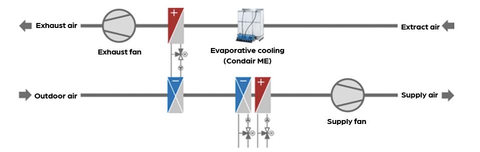
A schematic of the evaporating cooling process, with a run-around coil and supplementary heating and cooling to the supply air (Source: Condair)
Optimising airflow dynamics
From an energy perspective, it is important to consider not only the cooling benefit but also the associated fan and water pump energy.
In any evaporative cooling or heat recovery system, inserting heat exchangers and evaporative media (such as glass fibre pads or ceramic matrices) inherently obstructs airflow, creating an air-side pressure drop.
The additional fan power to overcome the additional system resistance results in an energy penalty in terms of increased electrical consumption. For a system to be cost-effective and sustainable, the energy saved by the evaporative cooling and heat recovery process must significantly outweigh the additional fan energy required to push air through the equipment.
To maximise energy efficiency, the evaporative and heat recovery stages should be bypassed under conditions where their thermal benefits do not justify the fan energy penalty, such as during ‘free cooling’ conditions, for example, when ambient outdoor temperatures are sufficiently low and the sensible cooling capacity of the fresh outdoor air alone can satisfy the building’s cooling demand.
Managing the bypass is typically handled automatically by the AHU’s control logic and mechanical dampers. In systems where physically bypassing the airflow isn’t feasible, integrated units utilise adaptive dry modes. In these scenarios, the air still passes through the heat exchanger, but the control logic locks out the water circulation pumps and sprays. While this doesn’t eliminate the air-side pressure drop, it significantly reduces water consumption and pump energy when sensible heat recovery alone is sufficient.
Exhaust air energy evaporative cooling
The suitability of EAEC varies with climate and application. In temperate climates such as the UK, where summer conditions are moderate and diurnal temperature swings are common, the technology can meet a substantial proportion of annual cooling demand. Analysis indicates that in a typical office building operating at a 22ºC set point, EAEC could satisfy around 55% of annual cooling requirements.1 This will be dependent on building type, occupancy and operating strategy.
In practice, the effectiveness of EAEC is highly dependent on operating conditions. In temperate climates, achievable supply air temperatures are typically limited to the high teens, and additional mechanical cooling is often required to meet peak comfort conditions. In hotter or more humid climates, while the system remains effective owing to its use of extract air, the overall cooling load is higher and hybridisation, employing additional cooling, becomes more critical.
While not a universal solution, exhaust air evaporative cooling offers significant benefits in a wide range of applications and climates, particularly when deployed as part of a hybrid system. And, when combined with other low-carbon technologies, such as heat pumps, it can form part of an integrated strategy for achieving net zero buildings. When applied appropriately, EAEC can deliver energy savings, reduce plant sizes, and support compliance with increasingly stringent environmental targets. As the industry continues to evolve, such approaches are likely to play a useful role in bridging the gap between current practice and the demands of a low-carbon future.
A practical example of EAEC implementation is provided by the MOBA manufacturing facility in Germany. The factory experiences high internal heat gains from machinery and processes, requiring substantial ventilation to maintain stable internal conditions for both workforce comfort and product quality. Conventional mechanical cooling was considered energy-intensive for such a large-volume space. Instead, the facility employs three AHUs incorporating exhaust air evaporative cooling. Extracted air from the factory, at approximately 24°C and up to 60% relative humidity, is passed through an evaporative humidifier. This increases the extracted air humidity to around 96% while reducing its temperature to approximately 18.9°C. The cooled extracted air then passes through a plate heat exchanger with an effectiveness of approximately 70%, pre-cooling incoming outdoor air to between 18°C and 20°C. This significantly reduces the load on downstream cooling systems. The impact on energy performance is substantial. The factory’s annual cooling demand is approximately 63,447kWh. A conventional system would require around 19,043kWh of electrical energy to meet this demand. With EAEC in operation, the additional energy required for evaporative cooling is approximately 497kWh, delivering around 26,447kWh of cooling. Total energy consumption is reduced to approximately 10,554kWh, representing a reduction of around 45% while delivering the same cooling output. This case study demonstrates the potential of EAEC to deliver meaningful energy savings in high-load industrial applications, particularly where large air volumes are required. However, it is unclear whether the 1,200Pa pressure increase on the supply fan and the 900Pa pressure increase on the extract fan due to the pressure drop through the evaporative cooler is included in the 10,554kWh energy reduction figure. It is possible to eliminate a significant proportion of the pressure drop by removing the evaporative cooling elements from the system in the months when evaporative cooling is not needed. However, there is no reference to this in this case study. The additional annual water consumption and pump energy would also need to be considered in the overall ROI. ‘Case
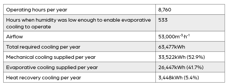
System operating hours per year.
Note: At this location humidity was only low enough to enable evaporative cooling to operate for 6% of the total operating hours
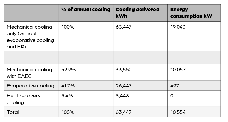
Annual energy consumption to deliver 63,447kWh of cooling