![]()
This CPD article will consider the increasingly demanding practical requirements for efficient and safe refrigerants that are ushering in pragmatic acceptance of the lower-flammability refrigerants, and methodology to ensure their appropriate application.
The vapour compression refrigeration system is employed in the majority of building services systems’ cooling applications, and is based on the basic simplified system as shown in Figure 1. (Although this article will refer to cooling systems, the same cycle and basic principles hold good for heat pump heating systems.) In a system, the cycle, as shown on the p-h diagram of Figure 2, will diverge from that of the simple cycle as indicated by the dotted line. This will depend on the specific system’s components and control, as well as levels of wasteful evaporator superheating, frictional resistances, pressure losses and heat losses. However, the fundamental process remains the same. The refrigerant transfers thermal energy between the colder evaporator and the warmer condenser by changing state both at the upper and lower pressures, generated by the compressor and enabled by the throttling device. (The basic system is discussed more fully in CIBSE Journal CPD module 2, available at cibsejournal.com.)
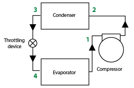
Figure 1: Schematic of a notional vapour compression system
The efficiency of the cycle can be described by the coefficient of performance (COP). The maximum theoretical efficiency is provided by the Carnot COP = Te/(Tc – Te) where Tc is the condensing temperature and Te is the evaporating temperature, both in absolute temperature, Kelvin. The value of the evaporating temperature will have the most significant impact on the COP, since it affects both the numerator and denominator of the equation, but generally for high COP, the (colder) evaporating temperature should be as high as possible and the (warmer) condensing temperature as low as possible. The difference between the two temperatures is known as temperature ‘lift’. In a real system, the COP is determined from the power ratio, (useful cooling, kW)/(compressor power input, kW) and is less than the Carnot COP due to the irreversibility of the pressure and thermal processes. The compressor power, described by the increasing ‘concave down’ curve 2-3, increases disproportionately with lift, and so increasing lift has an increasingly significant detrimental impact on COP.
Practically, the operating temperatures are driven by the application so, for example, if a direct expansion (DX) cooling coil is employed in an air conditioning unit to cool air, the cooling coil (the evaporator) will need to be at a temperature below the required air temperature (the actual temperature will be dependent on the heat transfer properties of the coil). Equally, if the condenser was rejecting heat into summer outdoor air, the temperature of the condensing refrigerant must be greater than that of the air temperature. To provide the best practicable COP, careful consideration is needed to establish, and maintain, an appropriately low temperature condenser heat sink (typically air or water), as well as establishing the highest evaporator temperature that will still provide the cooling and, often, the dehumidification required by the application. (And, of course, the efficiency that matters to the end user is the whole-year energy use, and the best way of improving that is to manage the heat load on the system so that it is used as little as possible.)
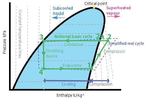
Figure 2: The vapour compression cycle plotted on a pressure-enthalpy diagram. This simple basic cycle includes constant pressure evaporation, isentropic compression, constant pressure condensation and (almost) adiabatic expansion (throttling) process
So, the operating temperatures set the key conditions required of a refrigerant. In vapour compression refrigeration systems, the refrigerant is a fluid selected so that it readily evaporates and condenses at the required temperatures, at pressures that can also be practically delivered and maintained in the system. There are many fluids – both synthetic and ‘natural’ – that can be used for this purpose, and as manufacturing and piping technology advances, the opportunity to safely operate at more extreme pressures allows novel refrigerant applications.
There are a number of parameters that are considered when evaluating a potential refrigerant that, depending on the application, are likely to include:
- Appropriate thermophysical properties – so that the system operates at acceptable pressures with low compressor input power and high refrigeration effect
- Environmentally benign – low global warming potential (GWP) and zero ozone depletion potential (ODP), with high COP to minimise primary energy use and indirect emissions
- Low or zero toxicity to occupants (directly or indirectly)
- Acceptably low risk of flammability. And in addition there are key operational requirements:
- Remains stable within the system and be compatible with system pipework and component materials (including high dielectric strength for hermetic compressors)
- Self-lubricating (or at least compatible with lubricants)
- Easy and safe to handle and detect
- Acceptable cost.
The evaluation of suitable substances is complex and practically includes multivariate analysis that has been led by manufacturers and research teams, including a team led by McLinden at the US National Institute of Standards and Technology (NIST).1 However, there are some fundamental properties that determine potential suitability.
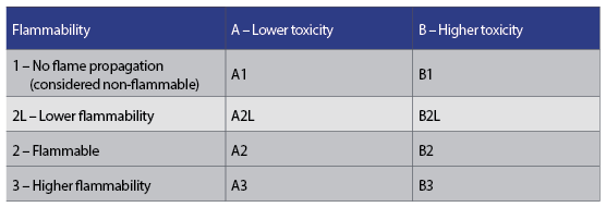
Figure 3: Standardised index of refrigerant flammability and toxicity
The basic thermodynamic properties of a potential refrigerant are the normal boiling point (NBP) and the critical temperature. A NBP – the boiling temperature at atmospheric pressure – below the required cold temperature will ensure that the evaporator operates at a positive pressure, so reducing the opportunity for the leakage of ambient air, non-condensable gases and water vapour into the system (which would all reduce the system performance). However, an excessively low NBP will increase the condenser pressure and density of the refrigerant vapour, which will increase the work required by the compressor.
The critical temperature of a refrigerant is that above which the vapour cannot be condensed into a liquid, no matter how high the pressure. This will be constrained not only by the application but also the geographic location since, for example, warmer climes will not be able to use refrigerants with critical temperatures below that of the high ambient temperatures. However, that same equipment could operate (more efficiently) in temperate areas with different refrigerants that possess a lower critical temperature. So, the refrigerant critical temperature must be greater than the condensing temperature, and considering the critical point (as shown in Figure 2), it is evident that to gain most benefit from the rejection of heat as the refrigerant condenses, the critical pressure must be appreciably higher than the condensing pressure so as to ensure that the enthalpy difference between 2a and 3 is as large as practicable. However, an excessively high critical temperature will reduce the volumetric refrigerating capacity (refrigerating effect per specific volume of refrigerant) due to increased vapour-specific volumes, and so will increase compressor displacement.
The refrigeration effect (line 4-1 in Figure 2) is determined by the proportion of latent heat of evaporation that takes place in the evaporator. Refrigerants that have a more upright p-h characteristic curve will utilise a greater proportion of the potential latent heat of evaporation that – in conjunction with the specific volume of the refrigerant vapour leaving the evaporator –determines the displacement (and mass flowrate) required from the compressor, and so the compression power. The heat transfer coefficient of a particular fluid, and its ability to move heat into the surfaces of the evaporator and condenser, will affect the area required for heat transfer, and so also impact the flow requirements and compressor power.
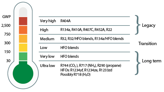
Figure 4: The GWP profile of current refrigerants (Source: Toshiba)
As well as meeting requirements to limit ozone depletion, the key environmental aspect that determines a substance’s suitability as a refrigerant is the potential impact on global warming that results from direct and indirect emissions, both in operation and production. (These are encapsulated in the concept of ‘life-cycle climate performance’.2) However, when considering the fundamental impact of a particular substance, GWP is the index that allows comparisons of the potential global warming impact of different gasses compared with CO2 over 100 years, as shown in Figure 4. The GWP of refrigerants is being limited by diktats including the EU F-gas regulations3 and the 2016 Kigali Amendment to the Montreal Protocol.4
This has constrained the available range of acceptable refrigerants, accelerating the development of refrigerants and increased application of ‘natural’ refrigerants –and, as suggested by the data in Figure 5, there is still some way to go.
The quest to employ environmentally benign refrigerants (that meet the foregoing thermophysical requirements) has intensified the need to examine and assess the risks of toxicity and flammability. Toxicity reflects the quantity or concentration needed to cause harm, and substances that pose a high risk in small quantity – even with short exposures – are regarded as toxic. Refrigerant flammability indicates its ability to burn or ignite, and will only occur if the volumetric concentration in the air is between the lower and upper bounds that provide conditions for flammability. The consequences of combustion depend on the burning velocity, heat released and byproducts of combustion. An index of risk of toxicity and flammability has been codified in international standards (including BS EN 378:20165), which is used to categorise refrigerants using standardised tests, and is shown in Figure 3.
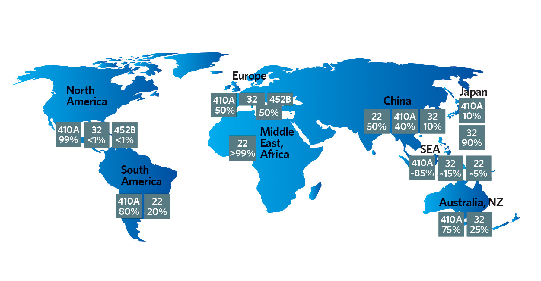
Figure 5: Estimation of current global refrigerant used in new systems, based on market reports (Source: ASHRAE webcast, ‘The Future of Refrigerants’ April 2019)
The chlorofluorocarbon (CFC), hydrofluorocarbon (HFC) and hydrochlorofluorocarbon (HCFC) refrigerants in use over the past 80 years have been safety flammability class 1. The flammability subclass 2L was recently introduced to provide better discrimination in the practical risk of flammability, specifically to provide scope for the application of refrigerants that would otherwise be categorised simply as class 2. Flammable refrigerants (class 2L and above) will not ignite if the concentration level is below their lower flammable limit (LFL). Legislation and standards define requirements that ensure concentrations remain below this in case of accidental leakage. In practical terms,6 it is very difficult to ignite 2L gases, and extensive investigations ‘have indicated that flammability of 2L refrigerants is acceptable for air conditioners and heat pumps’.7 However, this does not preclude a proper risk assessment since, for example, at the point of leakage the concentration will always be above the LFL – so a proper one is always required.
To limit the risk of toxicity, flammability and asphyxiation a refrigerant concentration limit (RCL), in kg·m-3, is set by BS EN 378:2016, which is used to establish the maximum refrigerant charge that may be used in a particular application. The standard accepts that the maximum leakage into an occupied space is assumed to be not greater than a pinhole leak, and the maximum charge is calculated on that basis.6 The calculation method accounts for normal and augmented room ventilation rates to maintain an acceptable RCL that are quantified respectively as the quantity limit with minimum ventilation (QLMV ) and the quantity limit with additional ventilation (QLAV) – both in terms of kg refrigerant charge per m3 of occupied space. The freely downloadable FETA publication, An introduction to A2L refrigerants and their use in Refrigeration, Air Conditioning and Heat Pump applications, provides some clear examples of how to evaluate acceptable RCLs for a particular room, in accordance with BS EN 378:2016. This accounts not only for the refrigerant toxicity and flammability, but also for characteristics relating to the specific application in the room.
Refrigerants with anything other than class 1 flammability should only be used in systems designed specifically to take account of their flammability characteristics. They should never be used to replace non-flammable refrigerants in retrofit applications without a full risk assessment and appropriate modifications.
© Tim Dwyer, 2019.
References
- McLinden, M et al, Limited options for low-global-warming-potential refrigerants, Nature Communications 2017 DOI 10.1038/ncomms14476.
- Guideline for Life Cycle Climate Performance, IIR, 2016.
- EC Regulation 517/2014.
- https://ozone.unep.org/news/kigali-amendment – accessed 11 May 2019.
- BS EN 378:2016 Refrigerating systems and heat pumps – Safety and environmental requirements, BSI 2016.
- An introduction to A2L refrigerants and their use in Refrigeration, Air Conditioning and Heat Pump applications, FETA 2017.
- Makhnatch, P, Understanding refrigerant flammability, KTH Royal Institute of Technology, 2015.