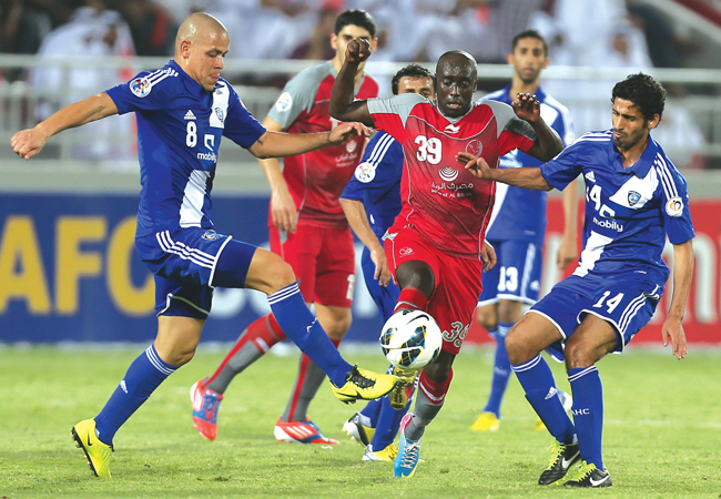
Credit: KARIM JAAFAR/AFP/Getty Images
Since Qatar won the bidding to stage the 2022 Fifa World Cup, engineers in the country have been researching the application of air conditioning in sports stadiums, using solar energy to supply some of the electricity for the cooling system.
The biggest challenges of air conditioning outdoor spaces – such as parks, holy sites and stadiums – are the difficulty of controlling the temperature and humidity, and the enormous amount of energy needed for the cooling system.
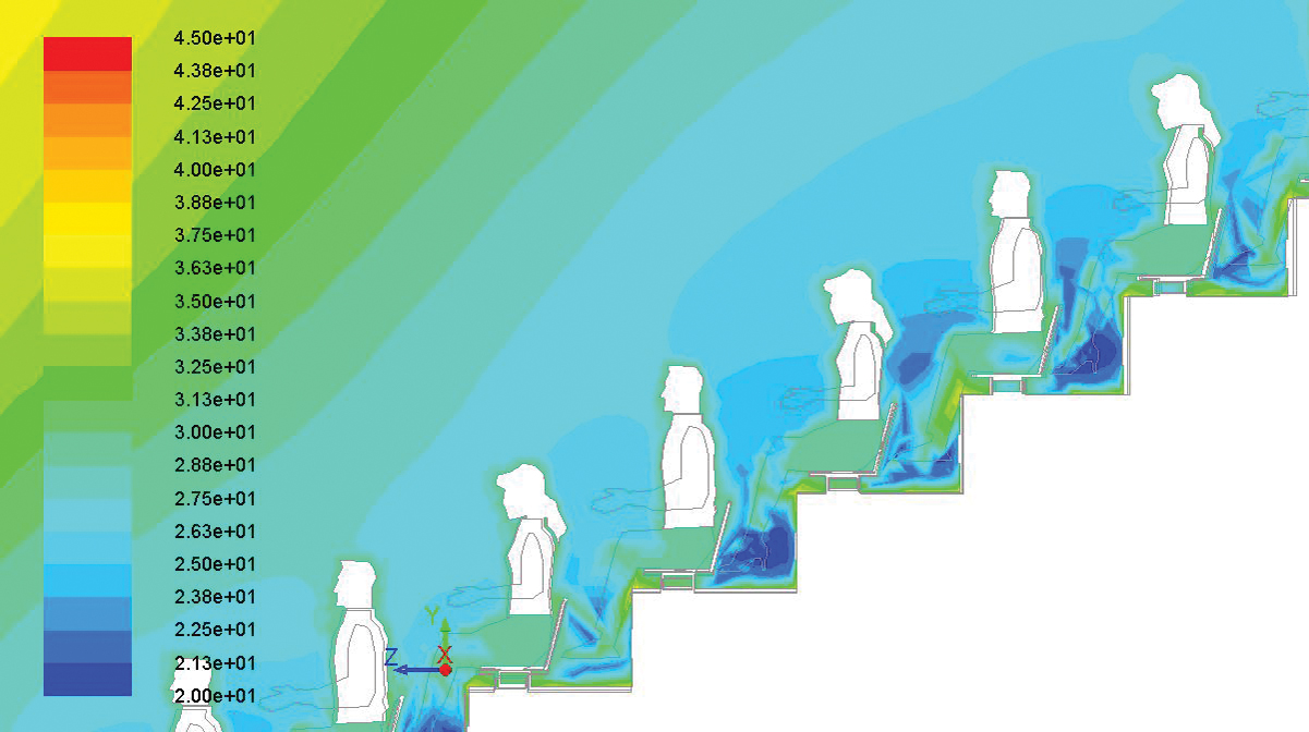
Figure 1: Temperature contours (°C) for Scenario 1
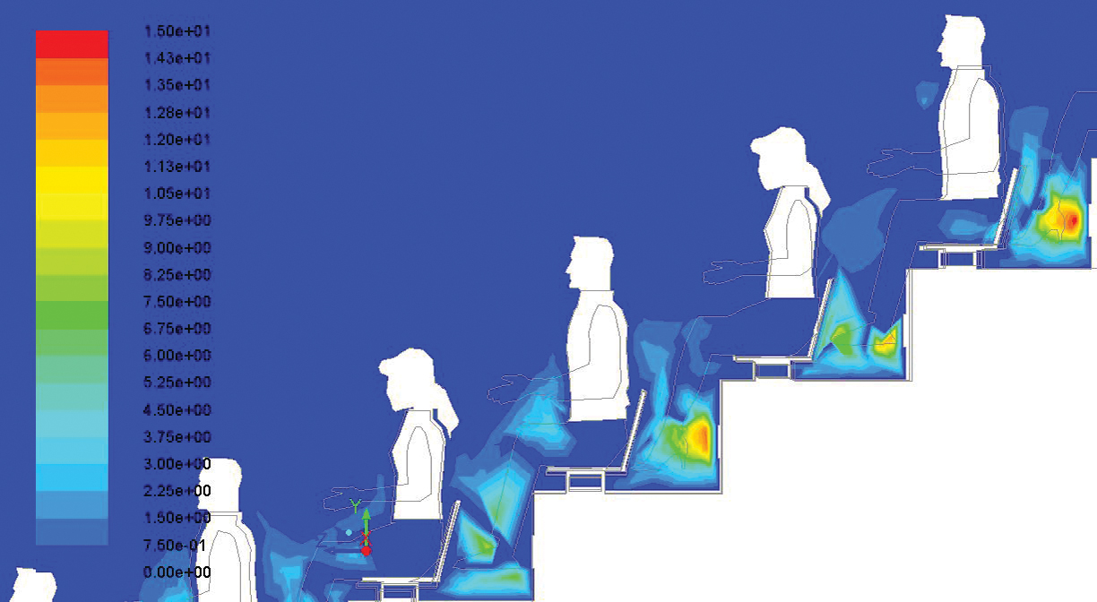
Figure 2: Velocity contours (m·s-1) for Scenario 1
Our research investigated the technical and economic aspects of cooling outdoor spaces, such as a football stadium in Qatar. The main task for the analytical model was to find a better method of distributing air to achieve thermal comfort for both the players and spectators inside the stadium.
Computational fluid dynamics (CFD) was used to predict the best way to distribute the air inlets and to simulate the airflow patterns to overcome the high ambient temperature and relative humidity.
The main objective was to create a simplified simulation model for analysing CFD results of the Qatari stadium’s air-inlet distribution to achieve the best circulation of air and predict its influence on thermal comfort.
The study considered parameters including ambient temperature, relative humidity, forced air velocity and solar radiation intensity.
The simulation results were used to validate the simplified simulation model, and find solutions and proposals to achieve thermal comfort.
Method
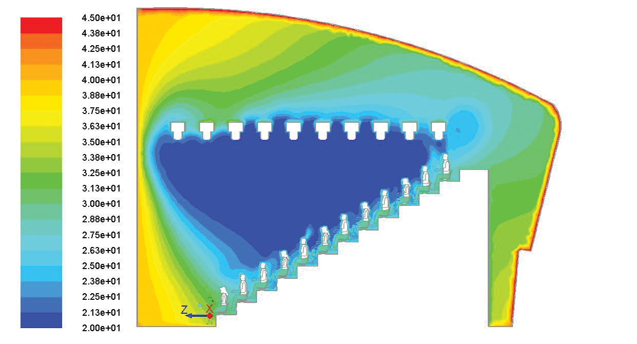
Figure 3: Temperature contours (°C) for Scenario 2
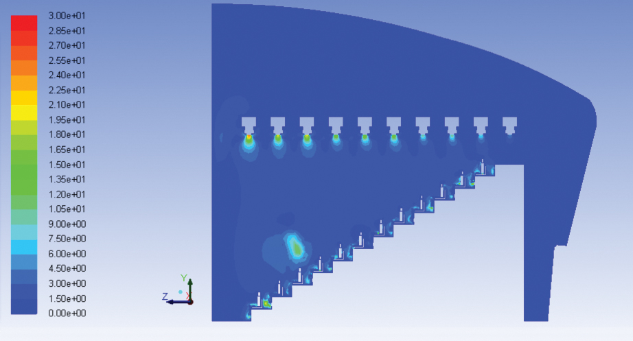
Figure 4: Velocity contours (m·s-1) for Scenario 2
CFD is often applied to various fluid-flow problems to predict a fluid’s properties, including flow velocity, density, temperature, and chemical concentrations for any area where flow is present in a model. In HVAC applications, distribution, speed and air temperature to create the best opportunity to achieve thermal comfort.
An optimised numerical grid was established for calculations. Orthogonal grids can be used, but they cannot represent curved and contoured shapes, so tetrahedral grid nodes – formed of triangle-shaped elements – were used. The grid had in excess of eight million grid nodes that gave converged solutions and grid-independent results.1
The study used two sets of calculations to simulate games that will be played in the afternoon and at night.
Lekhwiya Sports Stadium
The study was based on the 12,000 capacity Lekhwiya Sports Stadium – in the Duhail district of the capital city Doha – which is fully exposed to the 2,100 kWh·m-2 annual horizontal solar irradiance (compared with 1,000 kWh·m-2 in London).2
The locations of air inlets and outlets to achieve thermal comfort had to be selected in the spectator zone, and three methods of supplying air conditioning were examined using the CFD model.3-6
CFD was used to simulate three design scenarios in the spectators’ area:
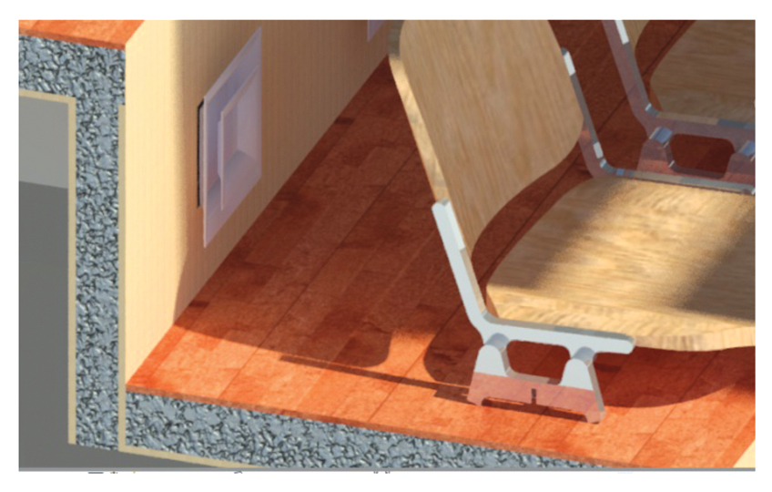
Seats made of wood or plastic would aid spectator comfort
Scenario 1: supplying cold air – at 20°C – from behind the seats with the velocity of 15m·s-1, taking into account that human skin temperature is about 27°C and the outside air temperature is about 40°C, speed 0.5m·s-1 and relative humidity 70%.
Scenario 2: supplying cold air from above the seats with velocity between 5 and 25m·s-1 and temperature of 18°C. The difference in the supply air velocity is a result of the difference in the form of the stands, where the seats in the front row are far from the locations of the air nozzles, and those in the last row are very close to them.
Scenario 3: supplying cold air from above the seats with velocity between 5 and 25m·s-1 and temperature of 18°C, and a radiant cooling system in the slab of the stands to absorb a proportion of the heat. The 15mm diameter embedded pipes are supplied with a mean water temperature of approximately 6°C. As before, the supply air velocity from the stands in the front row is 25m·s-1 and 5m·s-1 in the last row.
Results
This study investigated air distribution to achieve thermal comfort in many proposed simulation designs. In each case, velocity, temperature and humidity were predicted in the model.
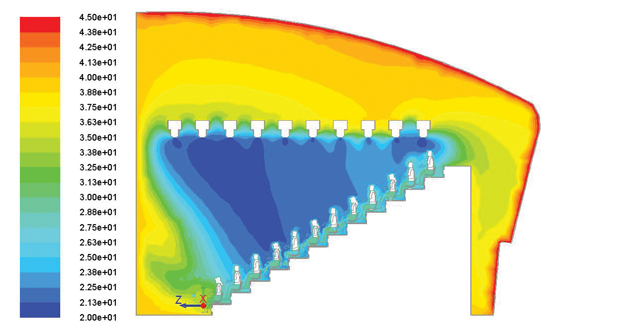
Figure 5: Temperature contours (°C) for Scenario 3
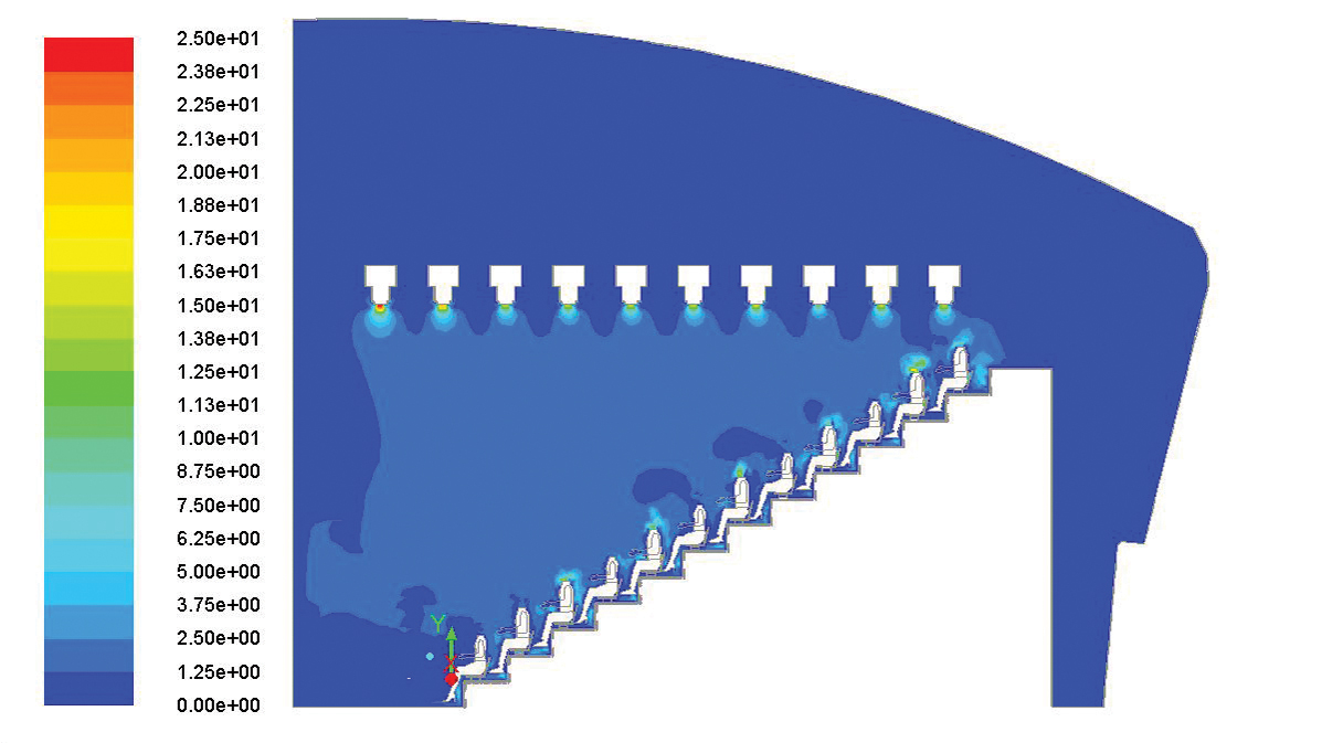
Figure 6: Velocity contours (m·s-1) for Scenario 3
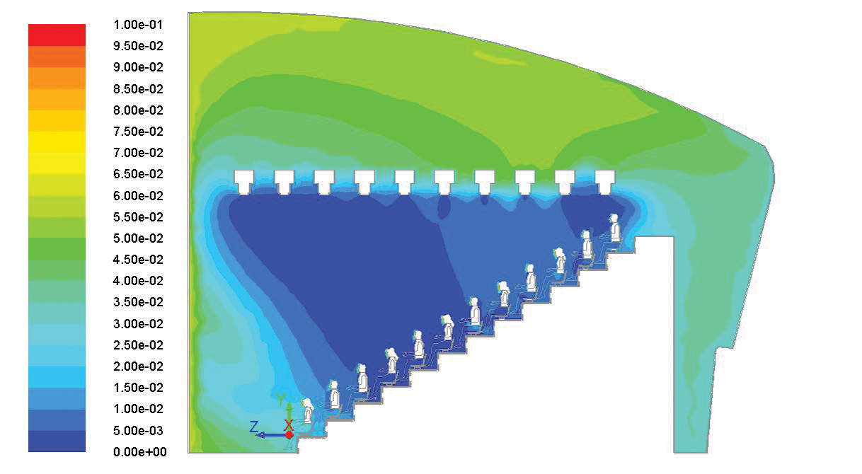
Figure 7: Humidity contours for Scenario 3
The results of the first scenario are shown in Figures 1 and 2, which identify air distribution inside the stadium and the effects of supplying cold air from behind the seats.
They illustrate that the distribution of temperature in the stands is not suitable, with the temperature of about 23°C behind the seats.
In addition, the chairs and spectators become obstacles for the cold air movement. Seats made of materials
such as wood or plastic – which do not store heat – were recommended to reduce opportunity for spectator discomfort.
The results of Scenario 2 consider the effects of a high level air supply, and air extracting from behind the seats. Figures 3 and 4 show the temperature and velocity contours for this case.
These figures illustrate that the temperature distribution in the stands is more suitable than that of Scenario 1.
In addition, the chairs and spectators don’t become obstacles to the cold air movement. Also it is notable that the humidity is relatively low in the stand areas.
The results of Scenario 3 show the effects of cold air supply from above and air return from behind the seats with radiant cooling in the stand slab.
Figures 5, 6 and 7 show the temperature, velocity and humidity contours for this case. The results show that the temperature distribution in the stands is more suitable than in Scenario 2, with the radiant cooling absorbing the heat and maintaining the temperature inside the stands. Here, neither the chairs nor spectators become obstacles to movement of the supplied cold air.
Summary
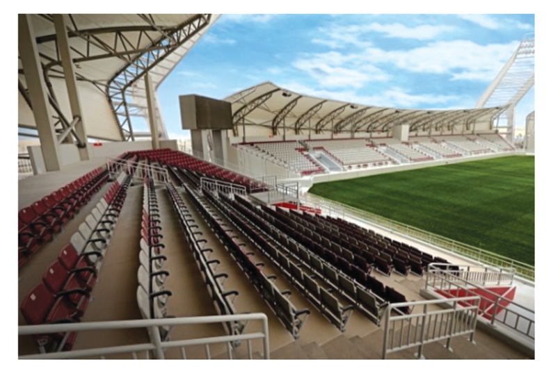
Lekhwiya Sport Stadium in Doha2
The study was conducted using CFD simulations to improve the air distribution in stadiums and achieve the target thermal comfort in three proposed designs.
In the simulations, results were obtained by changing the location of air inlets and outlets – and adding radiant cooling – before comparing the predictions in each scenario.
The results of the study concluded that the system designed for air conditioning a Qatari stadium was adequate to provide thermal comfort.
The main conclusions are:
- Installing supply air from above the seats with radiant cooling could improve HVAC performance in the stadium
- If Scenario 1 is incorporated, the chairs or furniture must be made from materials such as wood or plastic, which do not store heat. Materials that store heat – such as metals – may be harmful to spectators.
Essam E Khalil, FASHRAE, is professor of mechanical engineering, and Mohamed E Ashmawy a graduate research student, both at Cairo University’s Faculty of Engineering, Egypt.
References:
- Ashmawy, M E, 2016, Outdoor air conditioning: Qatar stadium, MSc thesis, Faculty of Engineering, Cairo University Giza, Egypt
- Lekhwiya Sports Stadium. Accessed 3 December 2015
- Jail, E, Using CFD for sports arena and stadia design, Ecolibrium, Oct 2004, 20-25, 160
- Abdulmoniem, H S, Abou El Kassem, E K and Khalil, E E (2011), Flow regimes and thermal comfort in air conditioned squash courts, IECEC Paper AIAA-2011-5961, August 2011, USA.
- Lestinen S, Koskela H, Nyyssölä H, Sundman T L, Laine T and Siikonen T, (2012), CFD simulation and measurement of indoor environment in a multipurpose arena, proceedings of Ventilation 2012: 10th International Conference on Industrial Ventilation, 17-19 September 2012, INRS, Paris, France.
- Khalil, E E, Air distribution in buildings, Taylor and Francis, CRC Press, USA, 2013.