Aberdeen City Council wanted its new exhibition and conference centre to be the most sustainable venue of its type in the UK. As a flagship project, it was essential that the energy strategy for The Event Complex Aberdeen (TECA) – now officially named P&J Live, courtesy of naming rights partner DC Thompson Media – embodied the city’s Sustainable Energy Action Plan.
There were also sound commercial reasons for it to do so: a low carbon footprint is increasingly seen as a critical component in attracting and retaining events at exhibition and conference facilities. The council’s brief to its development partner, Henry Boot Developments, was for a ‘zero carbon’ facility.
By its very nature, an exhibition and conference centre has an extreme energy-load profile. There is a peak load during an event, which drops to almost nothing between events. Unfortunately, it is not a load profile that typically lends itself to the application of renewable technologies. Moreover, the site is located close to Aberdeen airport, so there are restrictions on the use of large photovoltaic arrays, and severe restrictions on the height and location of wind turbines.
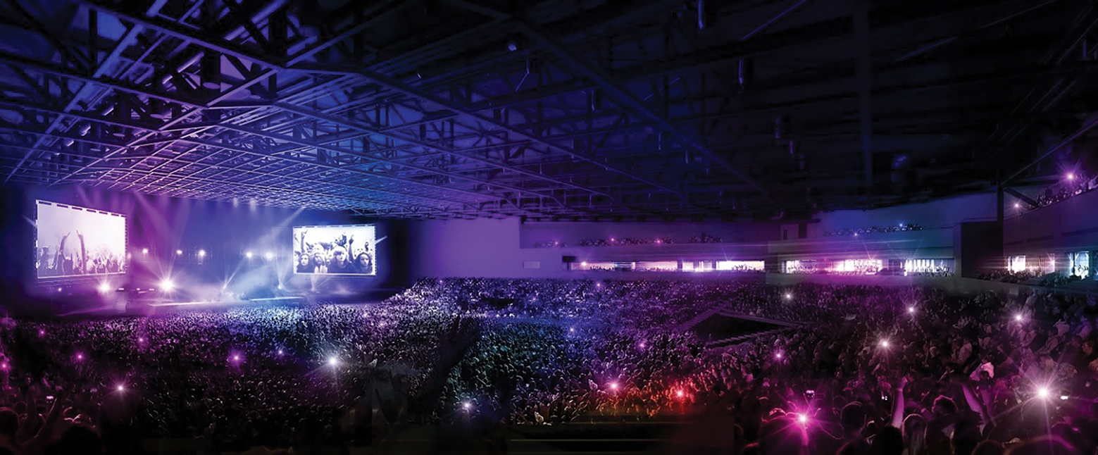
Visualisation of the 15,000-capacity arena
The task of delivering on this challenging brief fell to Henry Boot’s energy and engineering consultant HDR | Hurley Palmer Flatt’s Glasgow office.
‘We looked at the constraints of the site; wind and solar were not an option, so we had to figure out how best to develop an energy strategy,’ says Dr David Telford, director, energy and sustainability, at HDR | Hurley Palmer Flatt.
Designing an energy eco-system
The consultant’s solution is innovative and impressive in its ambition. It has developed what it terms an ‘energy eco-system’ to serve the exhibition and conference centre and two accompanying hotels, constructed adjacent to the facility.
The eco-system’s two principal components on the site are an anaerobic digestion (AD) plant and a combined cooling, heating and power (CCHP) generation plant, which is housed in the energy centre.
The AD plant takes food waste, agricultural waste and crops to produce a renewable biogas, which is then upgraded and cleaned by removing the CO2, moisture and impurities to turn it into bio-methane for injection into the gas grid. ‘The council had been looking at AD for food waste, but there was insufficient waste to make this viable, so we suggested co-fuelling the plant using crops,’ explains Telford. This solution ensures the digesters can provide enough gas to meet the total annual energy demand of TECA.
A dedicated combined heat and power (CHP) unit provides heat and power to operate the primary and secondary digesters and the gas upgrade equipment. The digestate remaining after AD is returned to the soil as a conditioner, completing the cycle.
Gas output from the AD plant is injected into the mains gas grid. It is an arrangement that enables the gas grid to be used as a fuel store, effectively, and enables the digesters to continue to digest, even when there is a low gas demand from TECA including its associated hotels. ‘We are injecting green gas into the Grid and taking green gas out of the Grid, so, effectively, we’re using the grid for storage,’ says Telford. There is also a bio-methane supply – sized to meet base load conditions – direct to the energy centre building next to the main arena.
The energy centre houses the CCHP system. Heat and power are generated using fuel cells and more conventional gas-CHP combustion engines. The localised generation provides a resilient solution for TECA by allowing off-grid operation.
Three 400kWe, stationary phosphoric acid fuel cells (PAFC) take the bio-methane gas supply, or grid gas, and ‘reform’ it to a hydrogen-rich gas, which feeds the fuel cells. In the fuel cell, the hydrogen-rich gas is combined with air in an electromechanical process, to produce a maximum output of 440kW of direct electrical current, heat and water. In fact, the fuel cells have been sized to provide sufficient electrical power to meet the total annual demand of TECA.
In addition to the fuel cells, the energy centre houses two 1MWe, conventional internal combustion gas-CHP engines, which are coupled to alternators and heat-recovery boilers. The hydrogen fuel cells and the gas-combustion CHP engines supply heat to the site’s four-pipe district heating and cooling network. Waste heat is used in an absorption chiller to provide the chilled water supply. The building also houses heating and cooling storage buffer tanks, and supplementary gas boilers and electric chillers to help meet peak demands.
The hydrogen fuel cells will give year-round base load heating and cooling, while the heating and cooling buffer tanks help address the daily demand variation. Seasonal variation is addressed through modulation of the CHP units.
Added resilience
The energy centre is also connected to the electricity grid, to add resilience and ensure sufficient power is always available to meet peak demand. At times of low demand, excess electricity is diverted to onsite hydrogen electrolysers and their associated compressors, to produce high-grade hydrogen fuel, which is used to power Aberdeen’s bus fleet. When the hydrogen store is full, electrical power is exported to the grid.
With so many different, complementary technologies available, a major challenge was to develop a control philosophy to ensure the heating, cooling and power demands of TECA, including the hotels, are met. In addition to ensuring loads are met, the philosophy had to enable the various low carbon technologies to operate efficiently and effectively, to generate maximum possible revenue from the sale of heat, cooling, power and hydrogen.
‘For the overall viability of the scheme, the whole technology mix had to achieve a reasonable financial payback,’ says Telford.
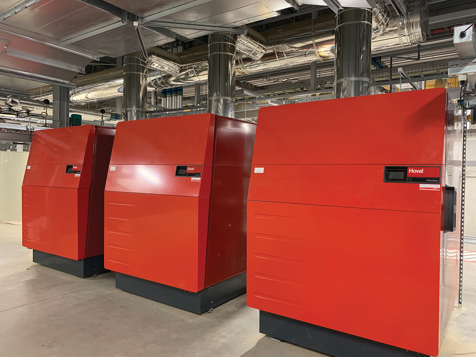
Hoval UltraGas gas-fired condensing boilers deployed as part of the heating system
To devise the optimal control solution, HDR | Hurley Palmer Flatt teamed up with the University of Strathclyde’s Energy Systems Research Unit (ESRU) under an Innovate UK-funded Knowledge Transfer Partnership (KTP). The project set out to develop an integrated suite of software tools to model and test hybrid energy centres against a range of demand profiles. The TECA project was used as a case study for the KTP, which received a B rating of ‘very good’. ‘We worked closely with academia to expand on the skills we already had in the office,’ says Mark Arthur, mechanical, director at HDR | Hurley Palmer Flatt.
The team was helped in its modelling by demand profiles provided by the original Aberdeen Exhibition and Conference Centre, which TECA has been built to replace. The team also sat down with TECA’s operators to discuss how they planned to use the facility – and which of the event and conference spaces were likely to be in use simultaneously – to build a predictive demand-side model. The modelling enabled the design team to test different operational scenarios, optimise plant sizing, and test the sequencing of different items of plant to best match its dynamic energy demand with supply.
‘New modelling techniques were developed to model the performance of the energy centre systems, enabling it to be reviewed at sub-hourly intervals across an entire year of operation, to optimise system performance,’ says Emma MacLeod, associate director at HDR | Hurley Palmer Flatt. (The control philosophy is described in ‘Control mission’.)
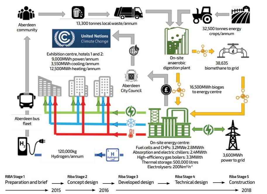
In addition to sizing the plant and devising the optimum control strategy for the development, the design consultant was appointed to carry out the detailed design for the energy centre using Revit modelling. ‘We’ve done everything from RIBA stage 1 “preparation and brief” to RIBA Stages 3 and 4, the “developed” and “technical design”; we even prepared the tender documentation for the FM contract under RIBA stages 6 and 7; “handover and close out” and “in use”,’ says Arthur.
TECA opened in August 2019 and, appropriately for an exhibition centre, the innovative energy eco-system is itself on show. The city council is using the scheme as a demonstration facility to showcase Aberdeen as a ‘world class’ centre of excellence for the global energy industry of the future – and with its new arena, exhibition and conference centre achieving net-zero carbon, the city is off to a great start.
Control mission
The scheme’s holistic control philosophy is best described by considering provision of power, heating and cooling separately:
Electrical power
Power is generated by fuel cells and CHP combustion engines.
- The three gas-powered fuel cells operate together to generate a total of 1,200kWe
- Fuel cell power generation is supplemented by the two 1MWe gas-fired combustion CHP units. These run only when there is a demand for heat. In winter, for example, if the demand for heat is high and power demand is low, the CHP engines will run at near full capacity, resulting in a power surplus
- If the surplus available is ‘low’ (less than around 36kW), power is sold to the grid
- If the surplus is ‘medium’ (greater than around 36kW), the power is used to operate the electrolysers to produce hydrogen
- If the quantity of surplus power generated exceeds the electrolysers’ maximum demand (around 1,060kW), the remaining surplus is sold to the grid
- Similarly, when the hydrogen storage is full, all surplus power is exported to the grid
- During periods when the power generated falls below demand, the shortfall is made up of power purchased from the grid.
Cooling system
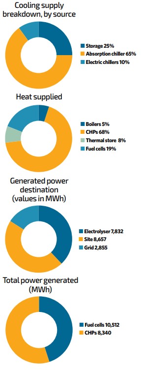
- Three main components make up the cooling system: a 400kW absorption chiller, two electric chillers with a total capacity of 2,000kW, and five chilled-water storage tanks, each with a capacity of 50,000 litres.
- First priority is given to running the absorption chiller, which operates on heat generated by the fuel cells. However, the absorption chiller has a minimum output of 200kW, so if the cooling load is less than 200kW, cooling demand is met from the chilled-water store, or the electric chillers if there is no chilled water stored
- At low load (200kW to 400kW), the cooling demand is met by the absorption chiller alone. There is an option to run the absorption chiller at a higher output than the actual cooling demand to recharge the chilled-water store if it has become depleted
- At medium load (400kW to 2,400kW), the absorption chiller is running at its 400kW capacity, with the remaining load met first by the chilled-water store and thereafter by the electric chillers
- At cooling loads above 2,400kW, the absorption chiller and electric chillers will run at maximum capacity, with the chilled-water store also being depleted as necessary. To ensure these peaks can be met, the chilled-water store will need to be charged in advance.
Heating system
- The heating system comprises three fuel cells with a total thermal output of around 600kWt; two gas-fired CHP units with a total thermal output of around 2,000kW, three gas-fired boilers with a total thermal capacity of around 3,000kW, and five thermal stores, each with a capacity of 50,000 litres.The first priority is given to using surplus heat from the fuel cells not being used by the absorption chiller, which means that the available heat varies from 340kWt to 636kWt
- At base load (300kWt to 600kWt), heat is supplied by the fuel cells, with the remaining thermal load met by the gas-fired CHPs. Any surplus heat produced by the fuel cells during base load periods is diverted to the thermal stores or, if these are at capacity, it is rejected to atmosphere
- At low to medium loads (600kWt to 3,000kWt), the thermal demand is met using fuel cells and the CHP units. The CHP controls allow both gas-fired CHP units to be modulated to satisfy demand within this range; any marginal differences between output and demand are absorbed by the thermal storage
- At medium load (3,000kWt to 8,000kWt), the heat produced by the fuel cells and CHP units is supplemented with heat from the thermal stores as needed
- At high loads (8,000kWt to 11,000kWt), the fuel cells, CHPs and thermal store are all in use, with any remaining load met by the gas-fired boilers
- At peak loads (greater than 11,000kWt), demand will exceed the combined maximum output of all heat generating plant. These periods are likely to total fewer than 24 hours each year. At such times, demand can be met by pre-charging the thermal stores in advance of anticipated peaks, and by ensuring that all heat from the fuel cells is used for heating instead of supplying the absorption chiller (the resulting cooling deficit can be made up by chilled water storage or electric chillers).
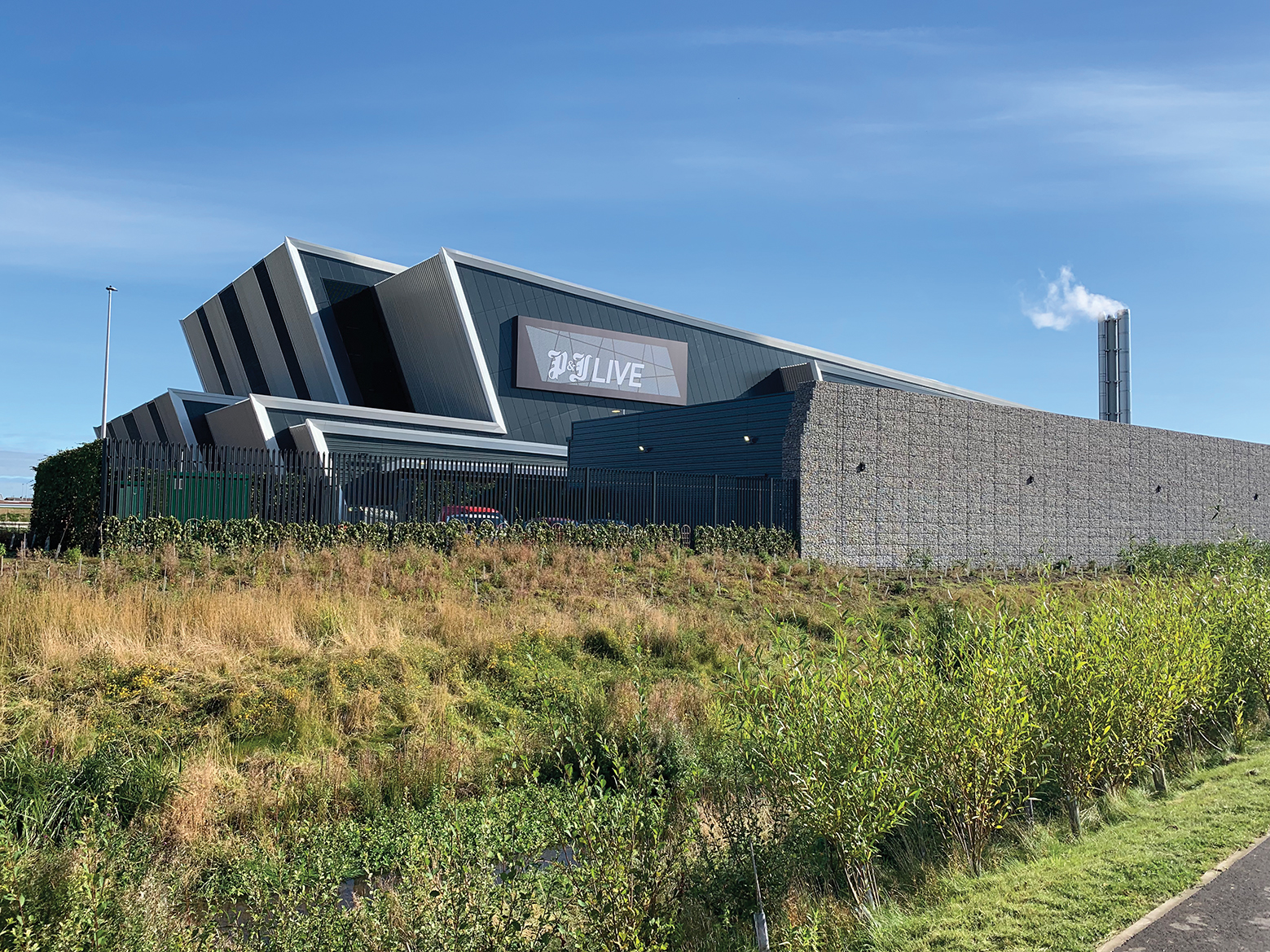
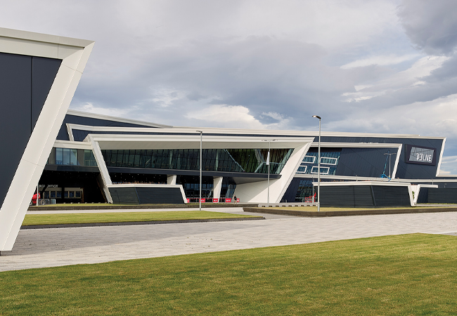
P&J Live now has the naming rights to the exhibition and conference centre
Project team
Client: Aberdeen City Council
Developer: Henry Boot
Architect: Keppies
Structural: Blyth and Blyth
Energy Masterplan and Energy
Centre M&E: HDR | Hurley Palmer Flatt
Hilton Hotel and Arena M&E:
Hulley and Kirkwood
Infrastructure and Aloft Hotel M&E: DSSR
Project manager: Turner and Townsend
Main contractor: Robertsons
M&E contractor: FES