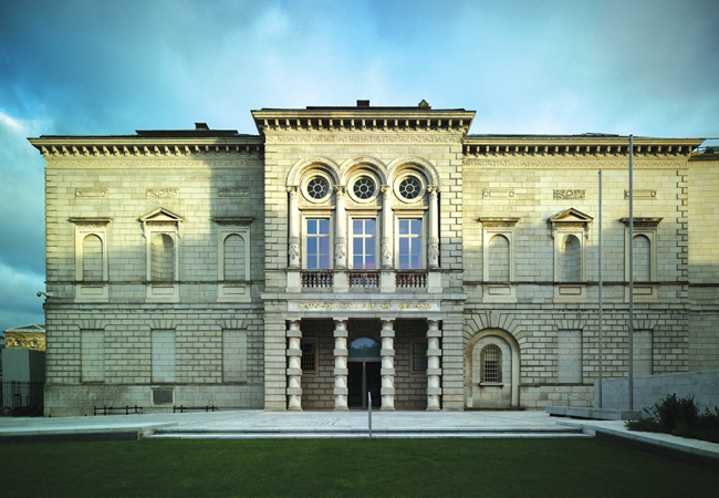
Supplying a historic building with modern services can be one of the toughest briefs a consultant can face. The refurbishment of the National Gallery of Ireland in Dublin was no exception.
Close environmental control of galleries containing priceless artwork had to be achieved without altering the building fabric or distracting visitors with unsightly distribution routes and air terminals. The main plant had to be located outside the galleries and no water services were allowed to pass through or near the gallery spaces.
There was a roof space that could be used for air handling plant, but it wasn’t large enough so the large ductwork systems couldn’t get in or out of the plant area. The historic glazed roof also had to be retained, which meant having to protect artworks from daylight and potentially 300kW of heat gains.
The brief required the environmental control to be as good as that of a new-build art gallery, and with better energy performance.
Existing services
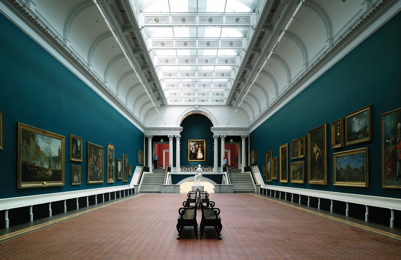
The project comprised the refurbishment of the Dargan Wing, completed in 1864, and the Milltown Wing, completed in 1903.
A network of cast-iron heating pipes provided background heating to the galleries, while quality natural light was a key feature of the original design – although some of the windows have been blocked up over time. These missing windows were rediscovered by the project architect and restored, to return the gallery to the naturally lit state first intended.
The 600m2 single-glazed roof of the Dargan Wing had to remain, which meant the daylight and heat gain needed to be tamed. As well as the effect of solar gain on air temperatures, BDP engineers were concerned radiant heat from the roof glazing would affect surface conditions of the paintings, while – in winter – radiant cooling would affect the canvas and frames.
The solution was to replace the large areas of glass within the gallery roofs with a high-performance glazing that incorporated micro louvres within panels. These louvres diffuse light to reduce peak solar radiation on paintings and have a UV transmittance of less than 1%. They produce a glazing g-value of 0.14, which reduces solar gains by 80% compared with the historic glazing. They also reduce heat loss by almost 70%.
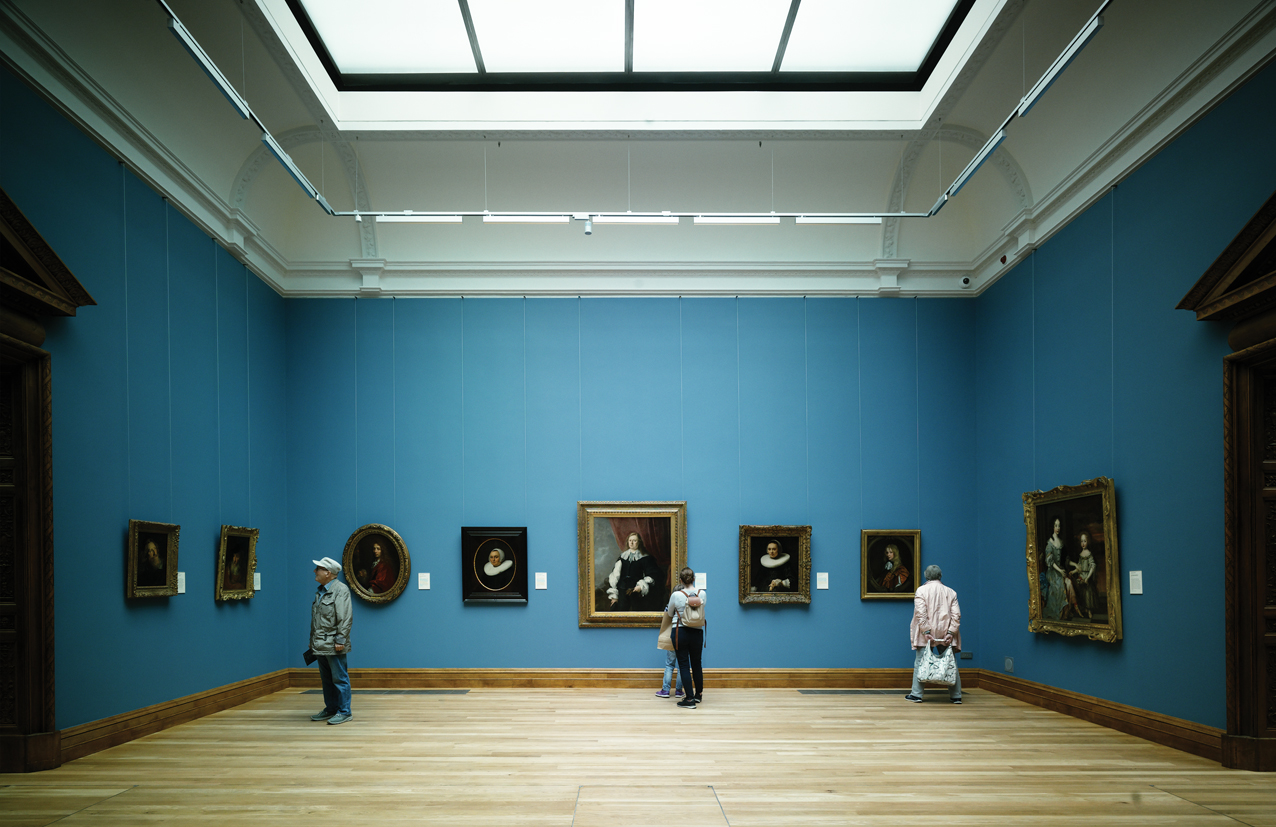
The top floor of the Milltown gallery is made up of a series of six inter-connected galleries of around 10m x 10m in size.
The roof of each space (known as a pod) is almost entirely glazed. The glazing is raised above the roof of the gallery to ‘pop-up’ above the roof. The glazing required additional consideration because a lower floor-to-ceiling height made the solar gain more critical. This glazing was divided into two layers to form a twin-roof construction, with controlled natural ventilation in between to moderate the glass temperatures (See Figure 1).
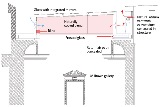
Figure 1: Milltown Gallery showing ‘pop-up’ roof and ventilation strategy
A blind was fitted between the layers of glass and can close automatically if the lighting level measured within the gallery reaches a level at which paintings may be damaged. The BMS can close these blinds during extremely warm conditions, to reduce system loads.
A new location was required for the heating plant, combined heat and power (CHP) unit, ice banks, fire-suppression misting system and electrical switchgear. The plant could not be put on the building’s roof so the decision was made to put it underground.
The plant room is hidden below the grass courtyard in front of the building (see main picture). It was possible to conceal some air vents in the vertical steps between the grass and the paving, while the two flues run 50m below the building to pick up a small, historic void leading to the roof.
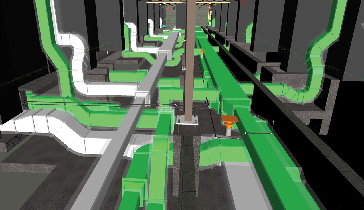
Use of building information modelling (BIM) was essential because of the limited space available for services. The roof air handling plant is a case in point, with a virtual game of Twister played until a satisfactory plant room arrangement was achieved.
The roof plant room available was roughly half the size that would normally be considered, and there was a significant change of level in the middle. Space was made even tighter by the main duct riser also being in the centre. The change in levels and central riser were addressed by folding the ductwork back on itself to pick up zone-conditioning equipment before heading down the risers.
Once on site, the mechanical contractor, Winthrop Engineering, quickly realised that a Revit model would allow improved analysis of the spatial requirements of the services systems and so it modelled large sections of the building.
Enhanced control
Galleries are traditionally controlled by a single sensor in each space, which can lead to local variations in conditions. These variations are normally minimised by supplying airflow rates that are much larger than required, continuously for the majority of the year. This over-provision of air is very costly from an energy and environmental perspective, but this is of secondary importance when control of environmental conditions is so vital.
In a historic building with voluminous spaces and large areas of glazing, local variations in conditions are expected to be more severe than in a purpose-built facility. An array of sensors was placed in each space and a bespoke control routine was developed to ensure they kept within range while minimising the air volumes. This reduced dramatically the fan energy required.
The control routine adjusts the temperature and humidity to maintain the centre-point condition (the midpoint of the highest and lowest sensor reading, not the average) at the required set point, then adjusts the air volume to control the bandwidth between these points at the condition limits. This method uses the minimum airflow possible to ensure all points are maintained within the acceptable band. A pressure-independent variable air volume system is then used to limit fan energy by minimising air volumes and fan pressures.
Several of the galleries are particularly tall to accommodate very large paintings, so sensors were also placed at high level, to monitor stratification and ensure the paintings are not subjected to significant variations in condition with height. With more sensors, there is a higher potential for them to fail or go out of range, or to be located in the wrong position for the hanging of a painting in a temporary exhibit. So a ‘hot swap’ solution allows a sensor to be unplugged for recalibration or replacement. The controls system will automatically detect that a sensor has been removed and adjust to compensate.
The sensors consist of probes mounted within wall pockets and measure an accurate air condition without any influence from the historic structure. It was important that the sensors were not visually intrusive and that the mechanism used to secure them was not visible. A bespoke solution used magnets to secure the face plates invisibly.
Distribution options
Horizontal distribution of services within the galleries was not possible, but a number of small, vertical distribution options were identified into which the supply ducts could be installed but with very little spare space. These included a void behind the stairs and a small recess where a window was once installed.
It was acceptable to form a new compact riser from the plant room to ground level, but not to exit the riser at any point within the building. The only logical option was to bury the new supply ducts under the building’s basement. This allowed the services to unfold and route directly below each of the galleries that they served.
Duct runs from the air handling unit to terminal units were up to 90 metres long. In conjunction with the response time of the gallery, the time lag between the control action at the plant room and the controlled space needed careful consideration. Fine-tuning of the BMS proportional integral derivative (PID) loops was required to obtain optimum balance between stability and response.
“Burying the new supply ducts under the basement allowed the services to unfold and route directly below the galleries they served”
The supply air to the Dargan Wing terminates largely behind the historic iron grilles placed under perimeter benching, which originally allowed heat from the traditional, exposed, cast-iron pipe heating system to enter the space. Discrete displacement grilles were fitted behind the historic ones, and the air distribution system is invisible to the visitor. In the Milltown Wing, new grilles have been installed in the original service voids in the ground-floor galleries, while floor grilles serve the first-floor galleries.
Finding routes for the air returning to the plant room was equally complex, as all the vertical risers had been filled with supply ductwork.
Return air from the large galleries on the ground floor was allowed to flow up the stairwell and through the upper galleries. While this avoids return air ducts, it introduces complex airflow patterns in the upper gallery that had to be verified in a detailed computational fluid dynamics (CFD) study.
Return air exits through existing openings in the ceiling decoration of the upper floor galleries, thereby avoiding the need for visible return grilles in most locations.
The main return air ductwork from the Dargan Wing was isolated from the plant room by a large glazed ceiling. The issue was how to incorporate ductwork across this space because even a hint of shadow crossing above the ceiling glazing would be unacceptable.
The pop-up pod glazing of the Milltown Gallery needed special consideration
The Baroque Room
Many an exasperated engineer has suggested to an architect the only way to meet the criteria for invisible services distribution is to construct the services from glass. In the case of the National Gallery, it was decided this was the best solution, and a glass duct was installed that allows return air to be transferred back to the plant room without being seen from the galleries below.
While the use of specialist glazing, variable air volume (VAV) air control and an enhanced enthalpy-based, free-cooling routine were implemented, the provision of 24-hour/365-day close control remains an energy-intensive process. So it was critically important heat and cooling was carefully selected.
The close control of humidity and temperature within a historic gallery needs year-round heating and cooling, which are either simultaneous or alternating within a relatively short time period.
A four-pipe heat recovery chiller allows waste heat from the cooling process to be used to reduce heating demand, but it can also operate in air source heat pump mode when serving a heat load alone.
“The system does not have a heat dump but is sized so all of the heat from the CHP is used”
Combining the chiller with an ice bank generates ice during the night, while the heat from the refrigerant condenser can be used when it is more likely to be required, because of cooler temperatures at night. The ice bank also smooths the electrical demand on the grid, which is important in a country that has set a target to achieve 40% of its electricity from renewable energy sources by 2020.
A 150kWe CHP system runs continuously and supplies the majority of heat for the refurbished galleries, with excess heat transferred to the adjacent Millennium Wing – existing galleries that did not form part of this project.
The system does not have a heat dump to remove any unwanted heat to the external air. Because galleries always have a de-humidification load, they have an all-year round reheat load that the CHP unit can serve if carefully sized.
Monitoring has confirmed that all of the heat produced is used within the galleries for heating, hot water and reheat as a function of the dehumidification process.
The efficiency of the electrical grid in Ireland is improving and, as it does so, the environmental benefits of the CHP unit will decrease – but the environmental benefits of energy from the heat pump will increase. The systems in the gallery are designed to change priority from the CHP to the air source heat pump as this transition occurs.
New supply ducts were buried in the basement
Results
We have been monitoring the galleries remotely for nine months. It has revealed an excellent level of temperature and humidity control has been achieved in the historic galleries.
“Visitors will be almost unaware of the intricate servicing system providing close control to the galleries”
The CHP has proved to be appropriately sized, with all of its heat usefully employed with the unit running continuously. Roughly 20% of the heat available is transferred to the adjacent existing Millennium Wing, helping to reduce the environmental impact there.
Very occasionally the output from the CHP unit dropped to about 80% of its maximum output when there was a control problem with the valve that sends excess heat to the Millennium Wing but it is clear from monitoring through a winter and summer condition that the gallery provides a meaningful load for the heat, all year round.
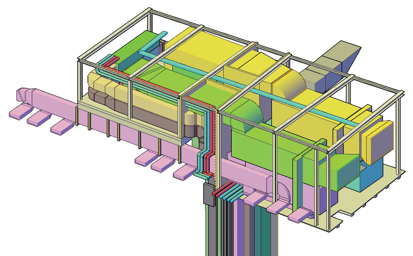
A BIM image of the uneven levels within the plantroom
For the first few months the contractor had set the CHP unit up to only run during the day but having spotted that we got it running 24 hours a day and then checked that the heat was still used during the night.
It wasn’t a surprise that all the heat was used as we had good data for the heat loads in the Millennium Wing before starting the design. This gave us an insight into what the additional loads in the refurbishment were likely to be (along with our simulations).
A visitor to the galleries will be almost unaware of the intricate servicing system providing close control to the galleries, with most of the equipment buried under the building and threaded through its structure. They can focus on the art, while the engineer takes care of the hidden services.
Project team
Client: The National Gallery of Ireland and the Office of Public Works
M&E: Building Design Partnership (BDP)
Architects: Heneghan Peng Architects
Conservation architects: Blackwood Associates
C&S: Michael Punch & Partners
QS: Aecom
Main contractor: John Paul Construction
Mechanical contractor: Winthrop Engineering