The key to effectively accommodating thermal expansion and contraction in a building services system is to allow the predictable, controlled movement of piping. This can be done in a variety of ways, and the selection of a specific method depends upon the engineer, the type of piping system and the project parameters.
Inadequate accommodation of this movement can result in business risks caused by excess stress on the piping system, including: increased incidence of ruptures and leaks; increased stress on boilers, chillers, valves and other equipment and components; and increased downtime and labour expenses. A grooved pipe-joining system is one way of accommodating thermal expansion and contraction. It reduces stress on the piping system and provides a more compact, easy-to-inspect, and productive method of installation over other pipe-joining methods, such as welding or flanging. In addition, with the grooved method, all sealing elements are combined within a metallic housing.
Stresses on piping
Thermal transients may impose stress on a piping system, as the pipe grows when heated and contracts when cooled. All materials, including pipe, experience dimension changes as a result of varying temperatures and their coefficient of expansion. This often occurs at directional changes in the pipework.
‘Bowing’ can also develop at the mid points of long, straight pipe runs, resulting in stress on the piping system and equipment.
When a system is subjected to changes in temperature, it may experience horizontal movement, vertical movement and angular deflection simultaneously.
Additional strains on the piping system vary based on whether the piping is vertical or horizontal.
For horizontal piping, the major obstacles are typically the space constraints around the length and turns of the pipe. For vertical piping, considerations are different, and should involve dynamic, static and elevation head calculations of the pressures and loads that are exerted on the bottom portion of the pipe.
Carbon-steel pipe will experience thermal expansion or contraction at a rate of 1.5mm for every 10K change in temperature, for each 10 metres of pipe. This puts the piping in a condition of stress, with potentially damaging reactive forces on components or equipment.
The forces generated during this thermal-dimension change are often significant, and the movement must be accommodated and controlled to prevent transmission of these stresses throughout the piping system.
Grooved solution
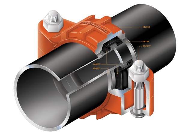
Grooved mechanical couplings enable movement in the pipe via design of the components. The dimensions of the coupling key are narrower than the groove in the pipe, allowing room for the coupling key to move in the pipe groove.
Additionally, the width of the coupling housing allows for pipe-end separation. This leaves room for controlled linear and angular movement. The mechanical coupling remains a self-restrained joint, and the unique pressure-responsive design ensures sealing even under deflection and pipe movement. (See panel, ‘What is a grooved pipe joint’.)
Grooved mechanical couplings are an alternative to welded U-shaped expansion loops, welded offsets, expansion joints and rubber bellows. These couplings are easier and faster to install, and accommodate movement within the design capability of the coupling.
Nonetheless, this takes place within the product’s ‘free range of motion’. Consequently, piping-system movement – caused by thermal expansion and contraction – can be accommodated in smaller spaces, with low stress on the components.
There are four common methods for accommodating thermal pipe movement in a grooved system:
- Providing an expansion joint using grooved mechanical pipe components
- Allowing the system to ‘free float’
- Using the linear movement/deflection capabilities of flexible grooved couplings
- Creating an expansion loop using grooved mechanical components.
- The method selected is dependent on the system type, the scope of the project, and the engineer’s preference.
Using expansion joints
Expansion joints are devices that can be compressed or expanded axially, and are generally the most costly alternative for accommodating thermal movement. A welded expansion joint flanged into the system requires regular maintenance. More cost-effective expansion joints use grooved mechanical couplings and specially grooved, short-pipe nipples with flexible couplings placed in long straight runs of pipe – these are pre-set to allow the required amount of contraction and/or expansion.
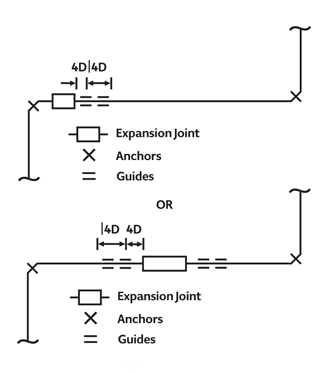
Figure 1: Design ensuring movement is directed into the device and no laternal movement is experienced
Axial movement can be adjusted by simply adding or removing couplings. When a series of flexible couplings are installed, the resulting grooved expansion joint will further protect equipment by reducing vibrations and stresses in the system.
Whether using speciality expansion joints or a grooved expansion joint, the adjacent piping must be properly guided (as shown in Figure 1) to ensure the movement is directed into the device and no lateral movement is experienced.
Grooved expansion joints may be used as flexible connectors; however, they will not provide full expansion and full deflection simultaneously. Expansion joints installed horizontally require independent support to prevent deflection, which will reduce the available expansion.
Flexible grooved couplings for linear movement and deflection
Grooved mechanical couplings are an alternative to welded U-shaped expansion loops, welded offsets, expansion joints and rubber bellows. Associated with a free-floating system, flexible couplings are used in piping systems to accommodate piping thermal growth – without the need for any additional components or piping configuration.
Flexible grooved-type couplings allow angular flexibility and rotational movement to take place at joints. These features offer advantages in installing and engineering piping systems, but must be considered when determining hanger and support spacing.
As illustrated in Figure 3, it is obvious that this system would require further hangers – or use of a rigid coupling – to eliminate the drooping of the pipes that would occur.
Hanger positions must be considered in relation to the angular and rotational movement that will occur at joints.
Flexible couplings can allow linear movement, so pressure thrusts must be taken into account. Considering this will allow the pipe ends to move to the maximum extent allowed by the coupling – this would have accumulated at the end of the system if the joints had been installed fully compressed or only partially opened when pressurised.
By using flexible couplings at changes of direction, and directing the movement toward the directional change with properly placed anchors and guides, movement is accommodated by the joining method itself. This method also produces little or no additional stress in the system, unlike a welded expansion loop.
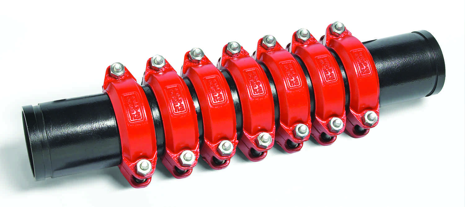
A series of flexible mechanic couplings
Flexible couplings also can be used strictly for their axial-movement capabilities. In this case, straight runs are anchored on each end and the piping is guided at every other length. Each flexible joint is pre-gapped – either fully gapped or fully closed/butted – at installation, to ensure that there are enough couplings to accommodate the expected expansion and/or contraction.
Flexible grooved-type couplings allow angular flexibility and rotational movement to take place at joints. In order to determine the appropriate number of couplings to use, the designer must compute the change in the linear length of the piping system by taking into account the length and size of the system, and maximum and minimum operating temperatures.
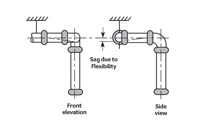
Figure 3: Sag due to flexibility
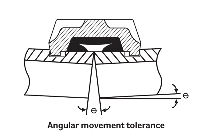
Figure 2: The angular deflection available at a flexible grooved pipe joint is useful in simplifying and speeding installation
Where full linear movement is required, a grooved expansion joint can be used, but joints that are fully deflected can no longer provide linear movement. Partially deflected joints will enable some portion of linear movement.
Standard cut-grooved pipe will allow for double the expansion and contraction – or deflection – capabilities of the same size standard roll-grooved pipe.
When considering offsets using grooved mechanical joints, the latter must be capable of deflecting sufficiently to prevent harmful bending movements at the joints.
If the pipes were to expand because of thermal changes, then further pipe growth would occur at the ends.
Flexible couplings do not automatically enable for expansion or contraction of piping. The designer should always consider the best setting for pipe-end gaps.
In anchored systems, gaps must be set to handle combinations of expansion and contraction. In free-floating systems, offsets of sufficient length must be used to accommodate movement without over-deflecting joints.
A grooved mechanical method can provide an efficient way to accommodate excess stress on any piping system. It eliminates incidents of ruptures and leaks because of thermal expansion, decreases the maintenance needs of equipment, and simplifies the commissioning process.
About the author
Larry Thau is executive vice-president and chief technology officer at Victaulic