
It is a somewhat daunting task for many building services engineers to assess an existing, formerly unseen, boiler installation when considering a replacement or enhanced system. Ideally, there will be schematic ‘as fitted’ drawings or digital models (and associated documentation), or operation and maintenance manuals that will be available for inspection prior to visiting the site but, particularly for older installations, the boiler plantroom will be the most reliable source of intelligence. However, boiler replacements are often undertaken as part of a more extensive building refurbishment, or the building may well have been altered in form or application since the boilers were installed, so any insight gained from the existing equipment must be considered in combination with a proper analysis of the building’s load requirements.
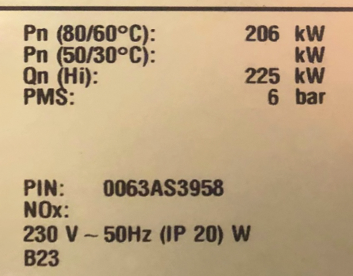
Figure 1: Photograph of boiler data badge
Before commencing any site activity, an appropriate health and safety assessment will have been undertaken and relevant enquiries and notifications made to those responsible for the installation, to ensure safe access (and egress) and that relevant personal protective equipment (PPE) is employed that meets both personal needs and site policies. Having ensured a safe working environment, and always being mindful of the risks in a boiler plantroom, an initial visual orientation should be undertaken in an attempt to understand the boiler configuration.
The boiler data badge can yield a significant amount of information. So, for example, the data badge shown in Figure 1 provides ‘Pn’ – the nominal rated output in kW at the stated flow and return temperature, while ‘Qn’ is the related nominal input (gas/oil) power. Dividing input by output power will provide an idea of the original boiler efficiency for estimation purposes (based on these specific nominal conditions). This particular boiler does not identify an output at 50/30°C – this infers that the boiler is non-condensing – an important consideration when considering the flue design.
Other data on the badge relates to the maximum operating pressure of the boiler (6bar); the power supply (230V @ 50Hz) and the ‘Ingress Protection’ (IP) rating (IP20 – touchproof, resistant to dust or objects that are over 12mm in size, but with no protection against liquids and susceptible to damage if it comes into contact with sprays of water); and the B23, which indicates that the boiler does not have a draught diverter, but uses a fan upstream of the combustion chamber/heat exchanger, and is designed to be connected to an open flue that will terminate vertically through the roof, with the combustion air being drawn directly from the plantroom.
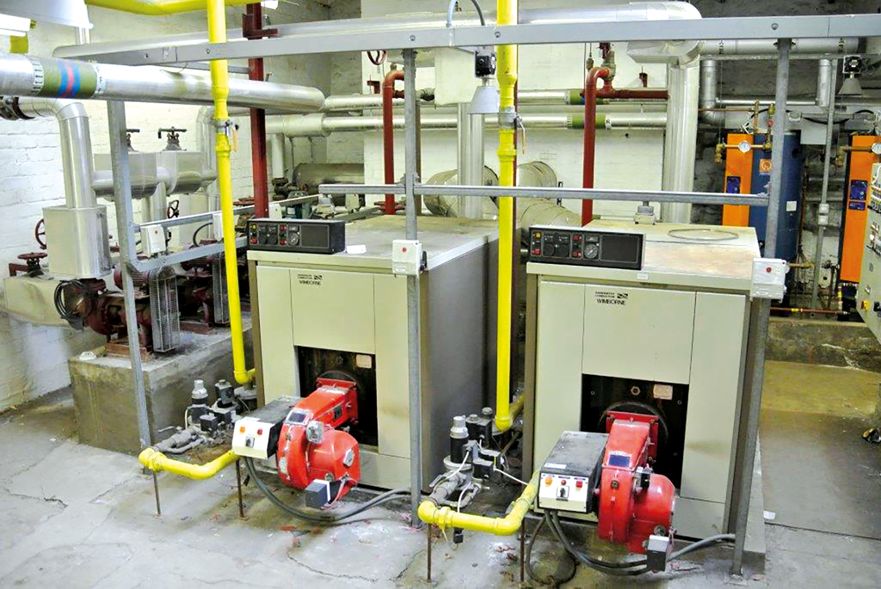
Figure 2: Two pressure jet boilers on a plinth with flue rising through a brick chimney
Typically in small and medium load installations, two boilers were often selected, with each boiler sized to cope with 67% of peak load and then operated on a duty/assist basis, as in the example of Figure 2. This illustrates two gas pressure jet boilers on a plinth (with the flue going off to rise through a brick chimney). The ‘gas train’ (the components that combine to safely supply natural gas to the boiler) for each boiler are to the left of the respective boiler connecting to the (red) burner assembly that contains the fan (blower), air/gas mixing section and control. The water-side connections are all made to the rear of these boilers.
The tracing of pipework, which is often complicated by the lack of pipe marking and obfuscated by enveloping insulation, may be undertaken through a combination of visual and thermal means (potentially aided by an infrared or contact thermometer). A simplified representation of a commonly encountered legacy piping system for a fixed volume, non-condensing arrangement, is shown in Figure 3. A main system pump (with standby) moves water from the reverse return header to serve the load. Each boiler has an individual shunt pump used when return water falls below approximately 60°C, to redirect high temperature flow back into the boiler return to prevent the boiler flue gas from condensing (as is increasingly the case when the boiler heat transfer surfaces drop below 55°C – these boilers are not designed for condensing operation). Although such constant volume flow systems may have been commonly designed on 82°C flow and 71°C return, extremely low return temperatures are likely to occur during periods of high demand, such as at system start-up. A common alternative to employing a shunt pump was to use a three-port valve in combination with separate primary and secondary pumping. The contemporary guidance was that if the return water required to be pre-heated prior to returning to the boiler for extended periods (for example, 20 minutes or more) a pump was preferred. So, three-port valves were typically employed on smaller systems with shorter warm up periods. These valves are typically known as back-end protection valves and are often thermostatically controlled to maintain a safe, condensation free, return water temperature.
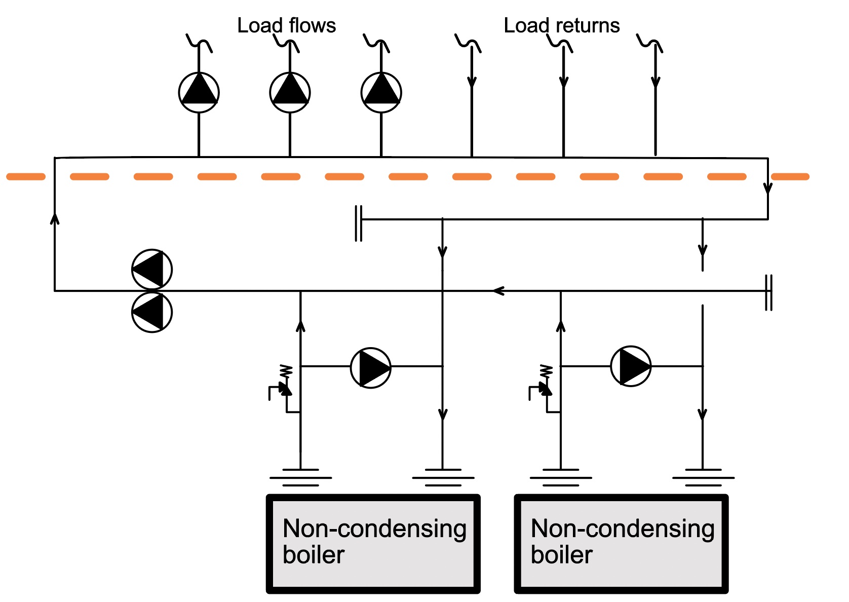
Figure 3: Typical outline schematic of existing non-condensing boiler installation
The purpose of the reverse return header was an attempt to balance the hydronic resistance of the two boiler pathways to allow easier commissioning.
Figure 4 shows where condensing boilers have been ‘dropped in’ to replace the old non-condensing boilers. The three-port valve has been removed, as the boiler is designed for condensing operation with a commissioning set often added to assist in the commissioning of the resistance of the replacement boiler. Frequently, it has been observed1 that the only additional work undertaken is the replacement of the primary pump set. (That would hopefully have been preceded with a full power flush of the horizontal header to remove accumulated sludge.)
A consequence of such an approach is ‘temperature dilution’. As an illustration of this, using the system of Figure 4, assuming that the replacement boilers are each 200kW, initially set to operate at 80°C flow and designed for a constant 60°C return (Δθ = 20K) with a minimum boiler turndown of 25%. (And obviously, at these temperatures, not operating in condensing mode.)
The primary temperatures may be examined by undertaking a simple assessment of a heat balance in the primary circuit and, by assuming a constant specific heat capacity, are approximated by considering a temperature balance of the flows. Referring to Figure 4, where θ is the water temperature (°C) and m is water mass flowrate (kg.s-1)
θf = (m1θ1 + m2θ2)/mf that, in fractional terms, where m1/mf = F1 and m2/mf = F2 and, in this case, as the flowrates through each boiler are the same F1 = F2 = 0.5, hence θf = (0.5θ1 + 0.5θ2)
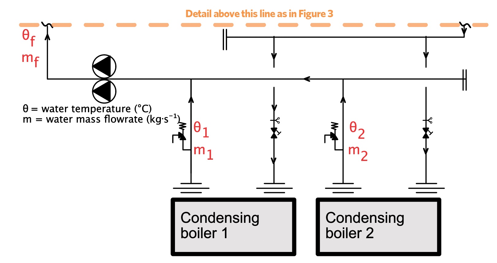
Figure 4: A simple replacement of the old boilers (shown in Figure 3) with new gas (condensing) boilers
Considering a 50kW part-load (while maintaining a boiler flow temperature of 80°C) so boiler 1 would be on (at 25%) and boiler 2 off – as boiler 1 is on, the 60°C entering water will leave at 80°C and boiler 2 is off, but still has water circulating through it, so the water will leave that boiler at 60°C. Provided that both boilers are in balance, the flowrate will split equally between each boiler and (on a first iteration) the combined flow temperature can be assessed as θf = (0.5 x 80°C + 0.5 x 60°C) = 70°C.
So, although the system is based on 80°C/60°C (that is, a 20K temperature differential) the system flow temperature is diluted to 70°C. Depending on the system side control, and accounting for it being a constant volume flowrate load, the return from the load could well be 50°C (or lower) that, although good for condensing operation, will act to further dilute (and reduce) the flow temperature, which then further reduces the return temperature, and so on. This will likely adversely impact the performance of the equipment supplying the load unless the load side has been adapted to work at a lower temperature. (A real application is likely to be rather more complex.) In an attempt to meet the required load flow temperature at part load, the boiler flow temperature could be increased to an extremely high 95°C (with a Δθ through boiler 1 of 35K). This would result in a combined flow temperature of θf = (0.5 x 95°C + 0.5 x 60°C) = 77.5°C.
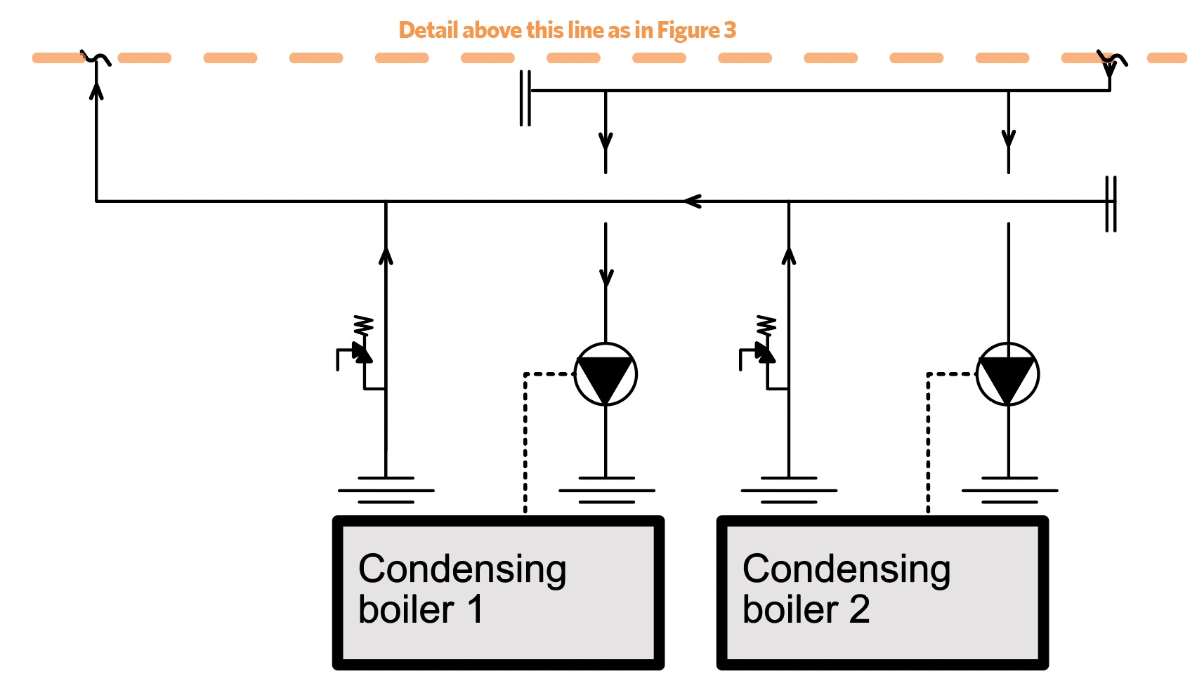
Figure 5: Adding shunt pumps with new gas (condensing) boilers to the system shown in Figure 3
This does not fix the issue, as this simplified example illustrates, since the boiler is only able to produce a blended temperature of 77.5°C. (This can become more of an issue when there are more boilers connecting into the primary system.)
An option to overcome this is to replace the main primary pump set with shunt pumps to each boiler, as shown in Figure 5. This will allow full load flow through either boiler so that there is no flow temperature dilution through a non-firing boiler. The shunt pumps may be on/off controlled from the boiler; however, they can also be controlled by the building management system (BMS). Controlling the pump via the boiler has the advantage that it allows the boiler to control run on, enable, and disable all from a simple signal from the BMS to the boiler, so simplifying the installation and mitigating the requirement for any additional points to be added to the BMS panel.
Alternatively, two-port valves can also be used with a common primary pump to isolate offline boilers. However, this would require the common shunt pump to be speed controlled via local pressure-sensing or BMS intervention. The two-port valve would also require control via the BMS, again adding some complexity to a potentially dated BMS panel.
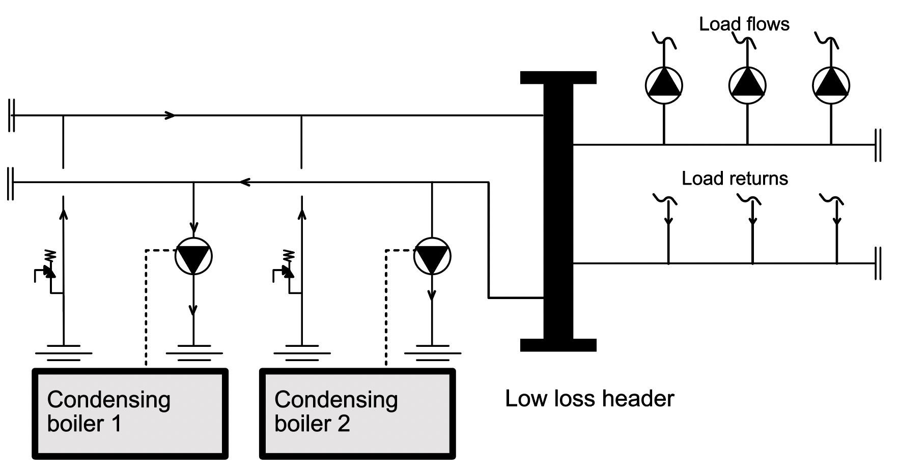
Figure 6: Decoupling the condensing boilers from the load using a low-loss header
An example of a more extensive solution, as illustrated in Figure 6, is to remove the reverse return arrangement and to hydronically decouple the primary and secondary circuits with a low-loss header (which can also readily combine air and dirt separation). The individual boilers are free to control themselves (overseen by the building control system). As the return water temperature rises, the variable speed boiler pumps modulate down to reduce the burner firing load, so maintaining a constant temperature differential.
The major advantage of this modification is that it decouples the generation and distribution side of the plant in terms of pressure and flow influence. The boilers are free to circulate through the low loss header without a direct hydronic influence of the constant volume load side and so the boilers can run with varying volume flowrates
A vertical low loss header can be used to improve air and dirt removal. The addition of vacuum de-gassers can also help remove excess air from the system, as this is a particular problem often seen in re-filling existing systems, as fresh (aerated) water will increase corrosion of existing pipework.
Wherever possible, to provide the most effective operation of the replacement condensing boilers, the load side should be critically examined, and potentially modified, in an effort to reduce the required water temperatures to ensure the gas boiler operates in condensing mode.
© Tim Dwyer, 2021.
■ With thanks to Ryan Kirkwood at Baxi Heating for the core information used in this CPD.
Further reading:
For a discussion of low loss headers see ‘Separate ways’ by David Palmer and Ryan Kirkwood in CIBSE Journal May 2021.
For a more comprehensive discussion of boilers and associated hydronics see CIBSE Guide B1 Heating 2016, particularly chapters 7 and 8.
To read about refurbishment needs and methods see CIBSE TM53 Refurbishment of non-domestic buildings, 2013, particularly section 4.1.
References:
- Collected private notes from field engineers – Baxi.