![]()
As discussed in CIBSE Guide B11 a hydronic heating system, regardless of size or complexity, can be thought of as comprising three sections: the primary circuit, which contains the heat generators; the secondary circuits that contain the heat emitters; and the hydraulic connection between the primary and secondary circuits.
The basic performance of the heat generator will typically be mandated through local regulations. For example, in England, the Non-domestic building services compliance guide provides the minimum requirements for ‘seasonal boiler efficiency’ for individual boilers and multi-boiler systems, for both new buildings and replacement systems.
These requirements are similar to those used across the UK and Europe. Additional credit, which assists in compliance, is given for system characteristics such as: ensuring installed boilers are sized not more than 120% of the building heating load; the use of multiple boilers in larger systems; providing controls that include appropriate implementations of weather compensation and optimum start/stop; and encouraging operation to be overseen by a building management system.
Guide B1 suggests that the design of the primary circuit, together with the control of the heat generator (and any associated pumps), should ensure the following requirements are met:
- The total heat output from the heat generators matches the heating demand in the secondary circuits reasonably closely
- The system is stable under all conditions
- Energy consumption/carbon emissions are minimised
- Thermal stress and acid corrosion of the heat generators is minimised.
As discussed in CIBSE AM14 Non-domestic hot water heating systems,2 modern boilers operate efficiently at part load. Historically, systems employing high thermal capacity boilers were designed to operate as close to maximum capacity as possible to reduce standing losses. High-efficiency boilers, which are the minimum standard for new and replacement installations, will have some – or all – of the following characteristics:
- Low water content and/or thermal mass
- Rapid response to demand
- Typically, stainless steel or aluminium heat exchanger with a multi-pass arrangement
- Peak efficiency at low firing rate (for both condensing and non-condensing boilers)
- A packaged modular arrangement
- Compact form, with high levels of thermal insulation.
Increasingly, in commercial applications, some – or all – of the secondary circuits will be variable flow, and that would typically be supplied from a primary circuit that is likely to include at least one gas-fired, condensing, low thermal capacity boiler. The basic performance of condensing boilers is directly associated with the temperature of the water entering the boiler’s condensing heat exchanger, as graphically illustrated in Figure 1.
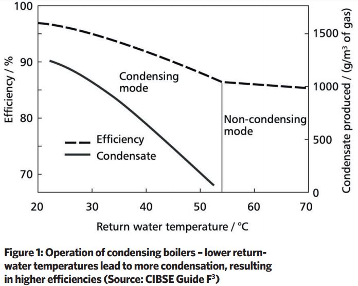
The lower return-water temperatures available from variable volume systems are particularly useful when condensing boilers are used, as their efficiency increases with lower return-water temperature. A note in the England Building Regulations compliance guide suggests that ‘condensing boilers will meet projected efficiencies only when they operate with a system return temperature between 30°C and 40°C for 80% of the annual operating hours’.
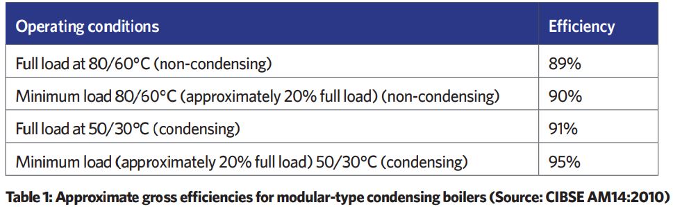
So, although high thermal efficiencies are attainable from currently manufactured boilers – as indicated in the examples from CIBSE AM14 in Table 1 – an inappropriate primary circuit design or control regime will prevent the highest efficiencies.
Most modern boilers, particularly those with low water content, require a minimum flowrate while they are being operated. The flowrate passing through the boiler will become smaller as the design temperature difference increases. However, there is a minimum flow required by the boiler to prevent ‘kettling’, overheating and potential heat-exchanger failure. Conversely, increasing flowrates beyond manufacturers’ recommendations will cause unreasonably high water-pressure drops, excessive noise, and can eventually erode system parts such as aluminium heat exchangers.
Most non-domestic heating systems incorporate more than one heat generator. In addition to providing a degree of standby capacity, this can result in improved overall system efficiency. Larger systems that require higher operating temperatures may benefit from having multiple boilers, with the lead boiler being a condensing type, and the remaining (potentially non-condensing, high-efficiency) boilers employed to provide heat only when peak loads (and higher temperatures) are needed.
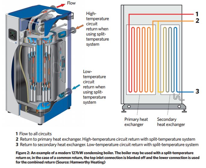
Alternatively, where there are loads in a building that can be divided into circuits of those with higher temperatures (above 56°C), and those with lower return-water temperatures, a condensing boiler employing a split heat exchanger – such as the example in Figure 2 – may be used.
As noted by Struck,4 at what were the traditional operating temperatures of 80/60°C flow/return, a condensing boiler will only achieve marginally higher efficiencies than a high-efficiency non-condensing boiler. If operating temperatures are reduced, typically to 50/30°C, or the temperature differentials can be widened to offer a lower return temperature (80/50°C), then there are significant opportunities for efficiency gains.
The lower return temperatures will increase condensation rates for condensing boilers, and maintaining a higher flow temperature will satisfy loads such as heating domestic hot water in a calorifier or through a plate heat exchanger. If using a boiler with maximum 20K differential, the flow temperature could be reduced to 70°C to allow 50°C return (enabling condensing operation); however, the heat-up times for hot water would be longer, or the heat transfer area would have to be greater to deliver the same performance.
By operating with a wider differential temperature and lower flowrates, the pressure loss will be reduced through a hydronic system. Considering an example commercial 250kW condensing boiler operating at a ‘traditional’ 11K temperature difference (Δθf-r) with a flowrate of 5.4L.s-1 would have a pressure loss in the order of 130kPa. Operating at 30K temperature difference would reduce the flowrate to 2L.s-1 with a pressure loss of just 18kPa (see boxout, ‘Heat generator power relationship’, for calculation method).
Pump power P (W), may be calculated from P = where Q is water volume flowrate (m3.s-1) and p is system pressure loss (Pa). So, for an 85% efficient pump, the peak pump power to move water through this boiler would reduce from 826W when operating at an 11K Δθf-r to 42W at 30K Δθf-r. This will deliver significant potential savings on pump capital and operational costs, energy use and environmental impact.
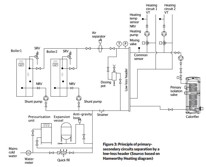
The interface between the secondary and the primary circuits should be designed to prevent the flowrate in any one circuit significantly influencing the flow in any other circuit. The increasing use of low thermal capacity boilers and variable flow secondary circuits has led to the widespread adoption of the relatively simple vertical low-loss header, as shown in the example circuit in Figure 3. (Alternative methods of hydronic separation between primary and secondary circuits may be provided by, for example, heat exchangers, buffer tanks, ‘close-coupled tees’ or, potentially, the more extensive Bodle-Orchard circuit.5)
The total pressure throughout the length of the low-loss header should be very nearly constant and so, by necessity, it has a relatively large hydraulic diameter with low-velocity water flow and low pressure loss. They are designed to provide a neutral pressure point in the system.
The commonly employed single vertical low-loss header normally includes an automatic air valve at the top and a purge connection at the base to remove the accumulated sludge. (In the May 2021 CIBSE Journal, David Palmer provides extensive discussion of the dimensioning of the vertical low-loss header.)
Undersized headers will not work as a low-loss header and will produce unwanted circuit interaction (where pumping in one circuit impacts another), whereas an oversized header –aside from taking up additional space and adding to cost – will not cause a significant issue and, if vastly oversized, tends to act as a small buffer vessel.
The primary pumps may be: integral to each boiler; as external pumps on each separate boiler sub-circuit; or as a single primary circuit pump. The choice of pumping arrangements must meet the requirements for load diversity and minimum flowrates, and the decision is likely to depend on a balance between system redundancy, controllability, and cost.
So, for example, in a critical application, such as a prison or hospital, redundancy over cost tends to be the primary deciding factor and may lead to the installation of individual pumps on each boiler sub-circuit. Condensing boilers are normally individually pumped because of their higher water-pressure loss and the need to maintain flow through the low thermal mass heat exchanger.
If a primary circuit has a single primary pump feeding multiple boilers, then a ‘reverse return’ pipework configuration should be used to ensure that flow is evenly distributed across all boilers.
Corrosion is controlled in condensing boilers by having suitable materials (stainless steel, aluminium or polymers) in contact with the cool combustion gases and condensate – some manufacturers’ pipework kits include this as a standard. Heat exchangers are often designed such that the flow of condensate helps to clean the heat exchanger surface, aiding efficiency and reducing the chance of hotspots or local corrosion pits forming.
The primary circuits for non-condensing boilers should be designed so that the average boiler water temperature does not fall below about 56°C – the dewpoint of the flue gas. Low-temperature boiler corrosion would be likely to occur at the smoke box prior to the flue connection and is often referred to as ‘back-end corrosion’.
Maintaining the return-water temperature above 56°C, along with keeping flue gases above 140°C, can provide protection from this type of corrosion – known as ‘back-end protection’. However, this can limit achievable burner turndown. At start-up, a thermostatically controlled bypass between the flow and return connections can be used to blend a small proportion of hot flow water with cooler return water, typically to ensure that the return temperature into the heat exchanger remains above 60°C.
Circulation is achieved either by a small shunt pump or by connecting the flow end of the bypass pipe to the primary pump discharge and controlling the flow/return blend through a three-port valve. In each case, the bypass is isolated automatically when the system return temperature reaches the pre-set minimum and, if fitted, the shunt pump is stopped.
‘Flow prevention’ (reportedly often confused with ‘back-end protection’) refers to the unwanted water circulation through inactive boilers (and other heat generators), which would otherwise increase the boiler ‘standing losses’.
Higher thermal mass boilers commonly employ a single primary pump to supply multiple modules. Flow through individual boilers may be controlled with a two-port isolation valve (potentially also employing variable flow primary pumping) or a three-port diverting valve for each module, integrated with safety control to ensure boiler overrun periods and to prevent excessive boiler temperatures.
For condensing boilers that, in any case, have significantly lower standing losses, flow prevention is typically effected by stopping the individual pump serving the module (subject to safety interlocks). As in Figure 3, a non-return valve is also used to prevent reverse-flow through the boiler when the pump is not operating.
Heat generator power relationship
The relationship between heating power, flowrate and temperature difference of a heat generator is given by equation φ = m Cp (θf–θr) where φ is the heating power of the heat generator (kW), m is the water flowrate through the heat generator (kg.s-1), Cp is the specific heat of water (4.2kJ.kg-1.K-1), θf is the flow water temperature leaving the heat generator (ºC) and θr is the inlet returning water temperature (ºC).
© Tim Dwyer, 2021.