
CIBSE Balham HQ
In recent years, the search for more reliable and sustainable energy sources has intensified. Though still on the brink of market entry, fuel cell micro-combined heat and power (CHP) systems for residential and small commercial applications have been proposed as one of the most promising innovations contributing to the transition towards a sustainable energy infrastructure.
With high electrical efficiency – more than 50% – and a low heat-to-power ratio, the system can run at high electrical and thermal efficiency throughout the year.
CIBSE has recently installed a solid oxide fuel cell (SOFC) micro-CHP system at its London headquarters – a converted, and recently renovated, Victorian townhouse – for testing and demonstration.
It aims to use this research project to build in-house expertise, and develop a body of knowledge in the form of publications, and other training material.
This case study, which I conducted with research manager Anastasia Mylona and Professor John T S Irvine, will look into the performance, availability and latest development of fuel cell micro-CHP systems, and the challenges and opportunities of introducing them into the UK market.
Initial results show the maximum heat recovered is about 1,000W at the return temperature of 15°C, and 300W at 45°C, which corresponds to an average combined efficiency of about 85%.
Micro-CHP systems
CHP, also known as cogeneration, is the simultaneous production of heat and electricity from the same primary energy source, such as oil, coal, natural or liquefied gas, or solar.
Until now, CHP plants have been large-scale units used for industrial processes and district heating, but progress has been made to apply micro-CHP as a substitute for high-efficiency boilers at domestic scale (with an electrical power below 5kWe).
A variety of micro-CHP systems are currently available, including: steam turbines, reciprocating internal combustion engines, combustion turbines, micro turbines, Stirling engines and fuel cells.
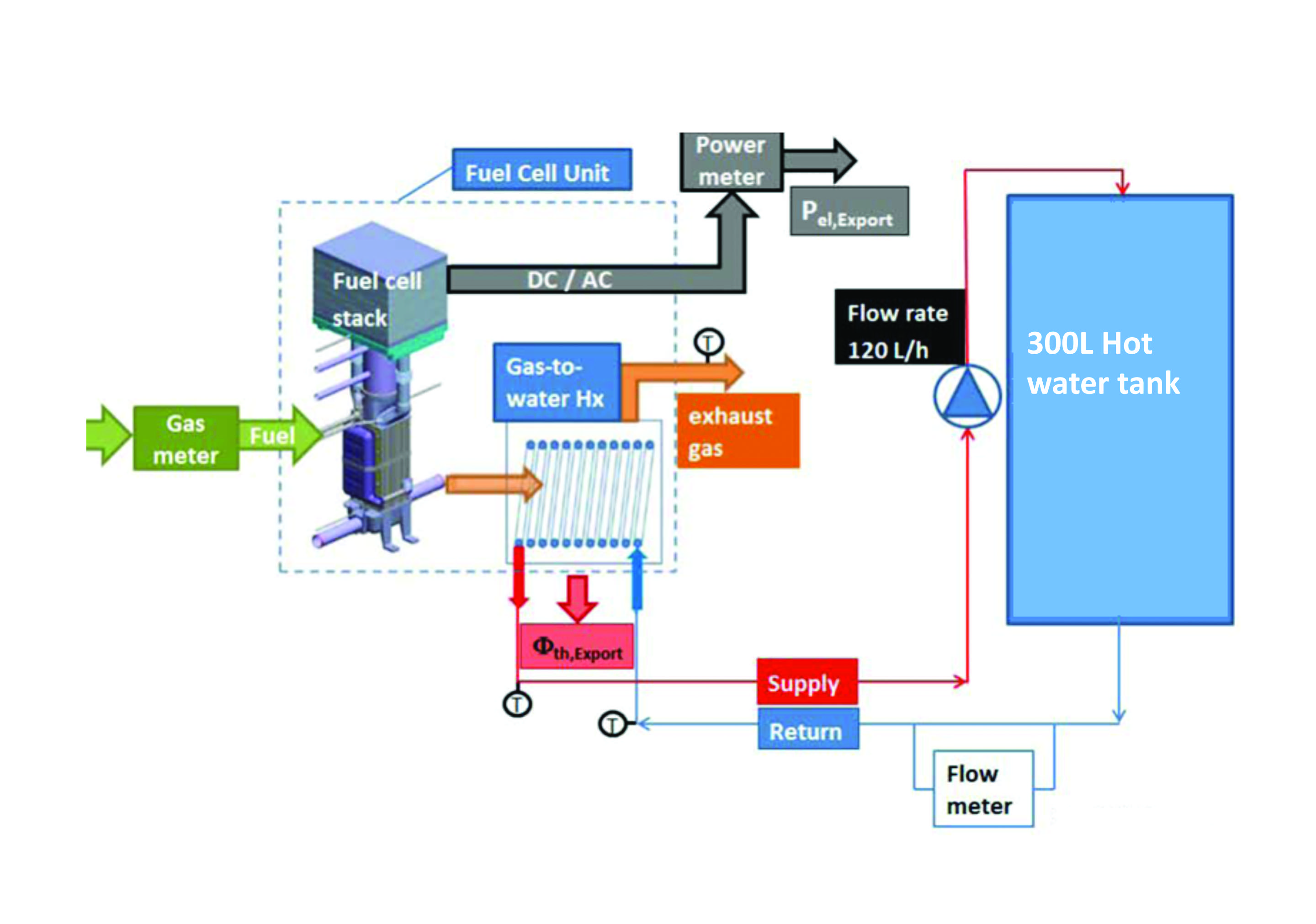
Figure 1: Schematic of fuel cell micro-CHP system arrangement adopted
The latter has been proposed as the most efficient way to convert the hydrogen – or hydrogen-rich hydrocarbons – to heat and power at the point of use for decentralised stationary power systems, and transport.
Unlike conventional fossil fuel power stations, which have many intermediate energy conversion stages, the conversion of the chemical energy in fuel cell systems takes place in a single step. Avoiding these intermediate steps reduces the irreversible energy losses and enables fuel cells to achieve efficiencies in the region of 40–60%.
These products could be used to meet the electrical and thermal demands of a building for space heating and domestic hot water and, potentially, for absorption cooling. Figure 1 shows a fuel cell micro-CHP system arrangement.
Selecting suppliers
During the selection process, the performance and reliability of several fuel cell micro-CHP products were compared, as well as availability and the supplier’s previous experience.
A lack of independent data to compare fuel cell micro-CHP systems meant the selection process was mainly based on the manufacturer’s ability to supply and maintain the system, as well as upfront cost and a good technical support system.
Presently, the selected system BlueGEN supplied by SOLID power is the only fuel cell micro-CHP product that has Microgeneration Certification Scheme (MCS) accreditation, so is eligible for the Feed-In Tariff that provides long-term financial support.
The micro-CHP system generates 1.5kW of electricity and about 200 litres of hot water a day, reducing both heat and energy bills.
The high electrical demand at CIBSE HQ – 25kWh – means all the electricity generated by the unit is consumed and none exported to the grid. Also, the 200l/day of hot water generated by the system is used to cover most of the 250l/day domestic hot-water demand at CIBSE HQ.
Market overview
One of the main obstacles to micro-CHP commercialisation is its upfront cost.
To succeed in the market, a fuel cell-based micro-CHP system must compete in performance and cost against rival technologies, such as Stirling engine-based micro-CHP, grid supplied electricity or combi-boilers.
Commercial secrecy and low production volumes have meant that price information for fuel cell micro-CHP is not widely disseminated. However, based on our research in the UK and other markets, currently a 1kW fuel cell micro-CHP costs about €16,000 (£12,000).
Achieving mass production and a technically advanced durable product is expected to reduce the price to about €6,000 (£4,500) by 2020.
In Europe and other parts of the world with similar climates, fuel cell micro-CHP systems are marketed as a heat and power system with combined efficiency of more than 80%.
By achieving 55-60% electrical efficiency, fuel cell based micro-CHP are still more efficient than centralised power generators. Currently, fuel cell stack life for both PEM and SOFC micro-CHP systems is reported to be around 80,000 hours, which is close to the system’s lifetime.
This would remove any fuel cell stack replacements during its lifetime, further lowering the overall cost. This indicates system durability is consistently increasing, showing the fuel cell-based micro-CHP may be technologically ready, at least for the market entry level.
But we have witnessed companies who supply such systems go into administration, with CFCL being the most recent. The importance of continuity for confidence building in the market place and in the wider public is critical.
Moving to a more sustainable energy systems such as fuel cells can only come from strong governmental leadership, giving confidence that would trickle down to the stakeholders and the market. More than 80,000 smart power units incorporating fuel cell technology have been installed in Japan, driven by the government’s objective to introduce 5.3 million units by 2030. This is also realistic in the UK, where smart power units are suitable for 90% of households and small businesses – equal to 22 million premises.
Installation issues to avoid
Often, gas systems have a solenoid valve connected after the main gas meter, which switches off the building’s gas supply in the event of a power cut. Any gas supply interruption would cause a forced shut down, potentially damaging the SOFC stack.
An external shutoff valve is unnecessary because the SOFC micro-CHP comes with its own safety features, and should be connected before the solenoid valve to ensure continuous gas flow. It is important to consult your system provider and installers about the safe gas connection to the system.
Water pressure within the building can also vary depending on the location, type and height of the property. The standard level of mains water pressure is 10 metres-head (or 1 bar).
Key connections
- A mains gas supply – All gas work and pipe fitting carried out should be completed in accordance with the relevant Gas Safe gas installation requirements
- The electricity grid – All unused electricity is exported to the grid. All electrical work carried out to connect the system to the existing electrical connections of the building should be carried out in accordance with BS 7671, and an approved kWh meter should be installed for the purposes of recording electrical output
- Mains water
- The internet, for unit control and monitoring.
It is therefore important to measure water pressure at the site before installation. If the pressure is insufficient to push the water to the furthest point of use in the building, a pressure-booster may have to be installed, which could add around £1,200 to installation costs.
The system should be optimised so that most of the hot-water demand is covered by the heat recovered from the unit, which can also be used for pre-heating.
The tank size and whether to include a backup heating system – such as an immersion heater, solar or a combi-boiler– will depend on the hot-water demand.
Hot-water temperature must comply with current regulation, and it is also worth checking the pipe size connections of the existing pipe system and make sure the new installation is compatible. To install the unit, the building will have to be connected to gas, an electricity supply, mains water and the internet (see panel ‘Key connections’).
While recovery of the heat produced by the unit is optional for operation, it is necessary – under MCS requirements – to make use of the heat for hot water to claim the Feed-In-Tariff available for CHP systems.
Electricity generation performance
The newly installed unit started generating electricity on 29 November 2014. To avoid damage and reduce stress on the unit, the power output was kept at 1.5kW.
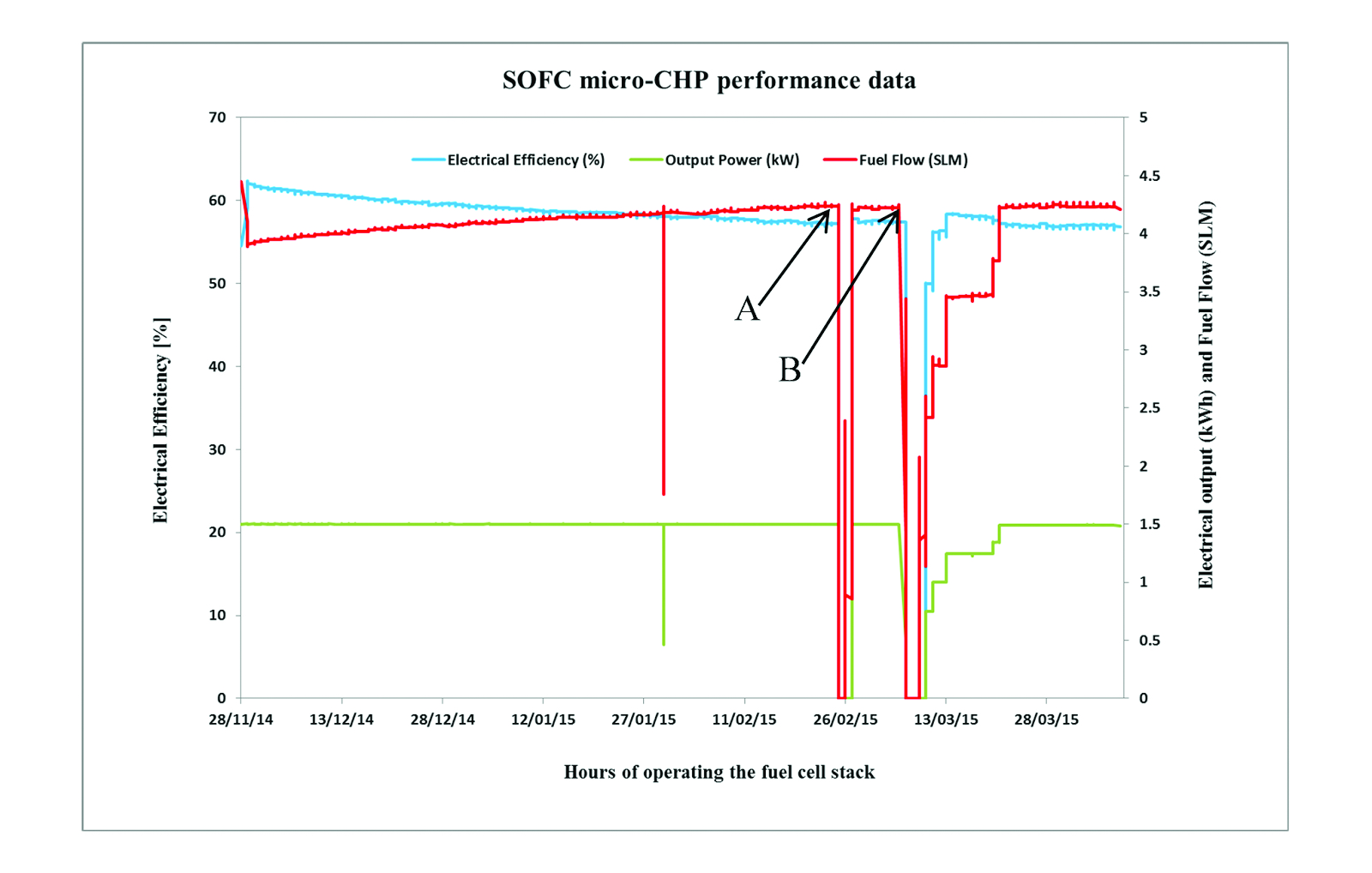
Figure 2
The base load electricity demand of the CIBSE building is 5kW, meaning all the power generated by the unit is consumed onsite.
The electrical efficiency data in Figure 2 shows that with a fuel input of about 2.5kW the system was generating 1.5kW electricity, giving about 62% electrical efficiency. With the additional heat recovery into domestic hot water, the overall efficiency is about 85%.
After five months’ operation, the electrical efficiency gradually dropped, stabilising at about 57%, indicating slight stack degradation.
As shown in Figure 2, at points A and B a power cut caused the safety solenoid valve to shut off the gas supply to the unit, causing a forced shutdown.
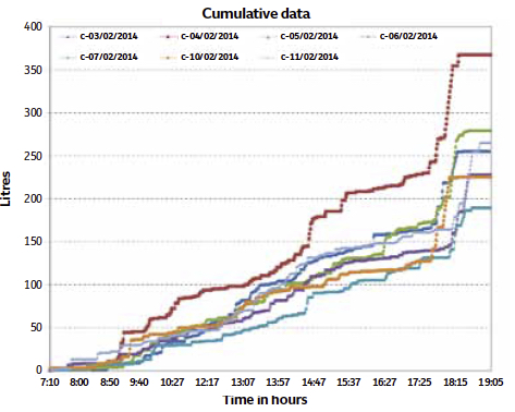
Figure 3: Seven days cumulative data showing hot water requirement throughout the day
As a result, at point A the unit was switched off for about 18 hours during which the temperature fell by about 200°C. After the stack was reheated and electrical production re-initiated, the system recovered well and continued generating electricity at 58% efficiency.
But, two weeks later another power cut interrupted the gas supply to the unit at 1am on a Saturday. During the three-day period that the gas was off, the stack temperature dropped by about 500°C.
Because of the big uncontrolled temperature drop, it was feared that the unit might fail to recover its pre-shutdown performance level, but it was nursed back slowly to its operating temperature, generating 1.5kW electrical output. Even after this second thermal cycling the unit maintained similar performance, reaching about 58% efficiency. Since then, the stack has been operating at almost 57% efficiency, with no major performance drop.
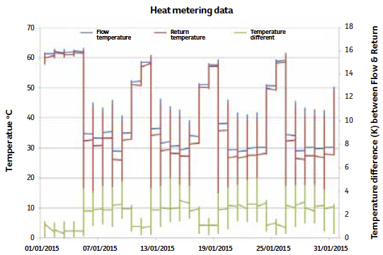
Figure 4: A consistent 3K difference between flow and return temperature shows high heat recovery
However, it is unknown whether the thermal cycling will affect the long-term efficiency and durability of the unit.
Heat recovery
Thermal performance of the fuel cell was tested at 1.5kW, where electrical power generation for this unit is most efficient.
CIBSE headquarters has three kitchens and seven toilets. As shown in Figure 3, the hot-water requirement varies throughout the day, averaging at about 250l/day, with most of the hot water used at about 5.30pm by the cleaners.
At that point – as shown in Figure 4 – the temperature can drop to about 16°C.
Figure 5: The flow and return temperature showing high heat recovery (3.5K) when the return temperature is about 15°C, and 1.5K when the return temperature is at 45°C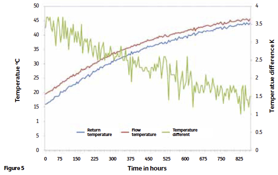
During the week, the hot water tank temperature moves between 35°C and 45°C (Figure 3). The data shows a steady 3K temperature difference, indicating good heat recovery. At the weekend, hot water tank temperatures reach about 60°C. From this point, the thermal output of the unit can only maintain temperature by compensating the heat losses of the hot water tank and the heat recovery loop. Starting from a return temperature of 15°C at around 6pm, the unit requires about 14.5 hours to raise the temperature of the hot-water tank from 15°C to 45°C (Figure 5).
From this point, the heat recovery loop temperature difference drops to about 1.5K. The fuel cell unit generates temperature differences of 3.5K at the beginning of the loading process, falling to 1.5K at the end of the loading process.
Figure 6 shows the comparison of the heat output flow temperature and the return flow temperature against the heat recovered in W. The result shows the maximum heat recovered is about 1,000W at the return temperature of 15°C, and 300W at 45°C, which corresponds to a combined average efficiency of the entire CHP system of about 85%.
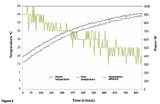
Figure 6: The flow and return temperature showing 1,000W of heat recovered when the return temperature is about 15°C, and 300W heat recovered when the return temperature is at 45°C
These results indicate the lower the temperature of the storage tank, the higher the heat recovery. To maximise heat recovery, return temperature should not exceed 45°C.
Conclusion
The SOFC based micro-CHP initially started generating electricity at 62% efficiency, and after the first 3,506 hours of operation its efficiency dropped to 57%.
Despite two forced shutdowns, it recovered well, indicating its robustness. But whether the forced shutdown will have a long-term effect on the durability of the unit is yet unknown.
The power production efficiency loss due to stack performance degradation is maintained at 1.5kW by increasing fuel flow from 2.5kW to 2.8kW. The thermal output of the unit depends on the flow return temperature of the heat recovery loop. The maximum heat recovered is about 1,000W at the return temperature of 15°C, and 300W at 45°C, which corresponds to an average combined efficiency of about 85%.
Selecting installers
The project plan and system layout were discussed and defined with all various installation companies that were invited to provide a quotation.
These ranged from £4,000 to £7,200, excluding VAT. The installers were selected based on price, MCS certification and the technical know-how, as well as previous experience in the installation of SOFC micro-CHP.
Experience has shown three key issues that need to be considered before embarking on the installation of the SOFC micro-CHP system:
1 What is the base load power requirement of the building (the minimum level of electricity demand)?
2 What is the domestic hot water requirement of the building?
3 Can the system be safely and efficiently integrated with the buildings current system or will it be a replacement to the current system?
System providers can help develop a business case, which will consider the heat and power demand of the proposed building. It is critical to explore different options for plant layout with as many system installers as possible to minimise installation time and cost.
The results clearly indicate that to maximise the heat recovery from the SOFC micro-CHP the return temperature should not exceed 45°C.
The mirco-CHP was successfully integrated to the existing heat supply technology, and heat recovered from the unit covered most of the domestic hot water requirement. Based on the initial performance, SOFC micro-CHPs could provide significant energy and cost -savings when used appropriately in an office. Based on current Feed-In Tariffs and energy prices the average return period of investment for a system like this is about 10 years.
Alem Tesfai is a fuel cell systems research associate at CIBSE KTP project linked to University of St Andrews