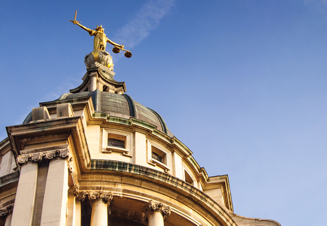
A 3.7m-high, gold-leaf statue of Lady Justice looks down from the domed roof of the Old Bailey building
Francis Capes, regional operations manager at Interserve Engineering Services, is walking down a long, dingy corridor in the basement of London’s Old Bailey. He walks past a row of dusty, drab, empty prison cells, at the end of which is a small, gloomy cell in which the only means of illumination is a tiny, dirty window set high in the brick external wall, above a sturdy door.
‘This is the condemned man’s cell; it is unusual because it has two doors – one from the corridor, through which you enter; the other to the outside, through which you leave to go to the gallows,’ says Capes, as he steps out into a small, sunken corridor.
‘This is Dead Man’s Walk,’ he says, gesturing at a series of arches that span the passage along which condemned prisoners must pass on their way to the scaffold. The openings in the arches get progressively more narrow. ‘They’re built to make the point that the condemned person is only going one way, never to return; it’s a cruel piece of architecture,’ Capes says.
Project team
Lead designer: Aecom
Project manager: WSP
Architect: HOK
Cost consultant: Gleeds
So begins the tour of the firm’s project to replace the central building services plant – the boilers, chillers and air handling units (AHUs) – in what is probably the most famous criminal court in the world.
It is heading the consortium, procured under a TPC 2010 Partnering Contract, to undertake the replacement project. The team includes lead designers Aecom, project managers WSP, architect HOK and cost consultant Gleeds.
The original court building, which is owned and managed by the City of London Corporation, was erected in 1907. Parts of it were rebuilt after bomb damage in World War II, then – in the late 1950s– the facility was substantially extended and remodelled. Most of the building services plant dates from around this time.
The existing oil-fired steam boilers in the plantroom
Standing in Dead Man’s Walk, Capes points out two new heating mains running the length of the passage, which were installed under the project. He also gestures towards three new, black-coloured boiler flues that rise up from a new basement boiler house to the building’s roof, six storeys up. ‘These were installed under Phase 1 of the project,’ he says, ‘Even though they are not visible from the street, we still had to have the planners’ approval for them – which is why they’ve been painted black,’ he says.
The £38m refurbishment/replacement project is split into five phases, which will be completed sequentially over a period of 10 years. Work has to be phased to avoid disruption to the criminal justice system. ‘A decision was made at the outset that only two of the six courts in the 1907 building could be out of use at any one time in phase 2, and one of the 13 courts in the 1960s building at any one time going forward. It is these closures that dictate the duration of the programme,’ explains Richard Morgan, associate director, building engineering, at Aecom, and Capes’ wingman on the tour.
Interserve has been on site since January 2015. With Phases 1 and 2 successfully completed, it has just started work on Phase 3, in which the existing plant serving courts 5, 6, 13 and 14 will be replaced with six new AHUs during a 12-month programme.
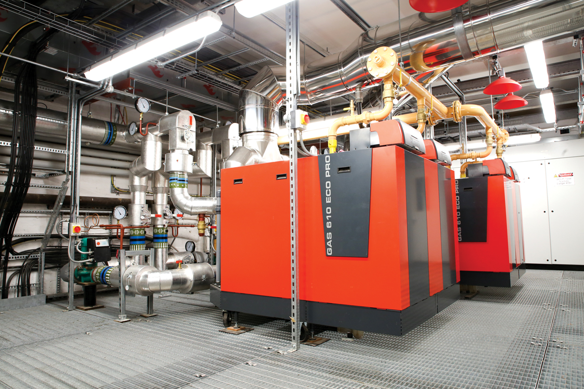
Before taking in the Phase 3 works, Capes’ tour continues with the works completed under Phases 1 and 2. From Dead Man’s Walk, he re-enters the building to descend to the sub-basement. Here, in Phase 1 of the project, the firm created a new gas-fired boiler room in a space that – in 1908 – housed the building’s coal-fired boilers.
New sub-basement boiler plant
‘It was filthy in here,’ says Capes. ‘We took out what remained of the old coal boiler room and put in a louvre to create a new boiler room.’
Adjacent is a newly created pump room, reclaimed from a ‘dirty, horrible and smelly’ disused oil-tank room.
All of the noisy work in converting the boiler house and pump room had to be done out of hours. ‘We’re allowed to do noisy work before 9am, at lunchtime (between 1-2pm), and then after 5pm,’ says Capes. ‘Sometimes we have to work weekends and, sometimes, we work through the night.’
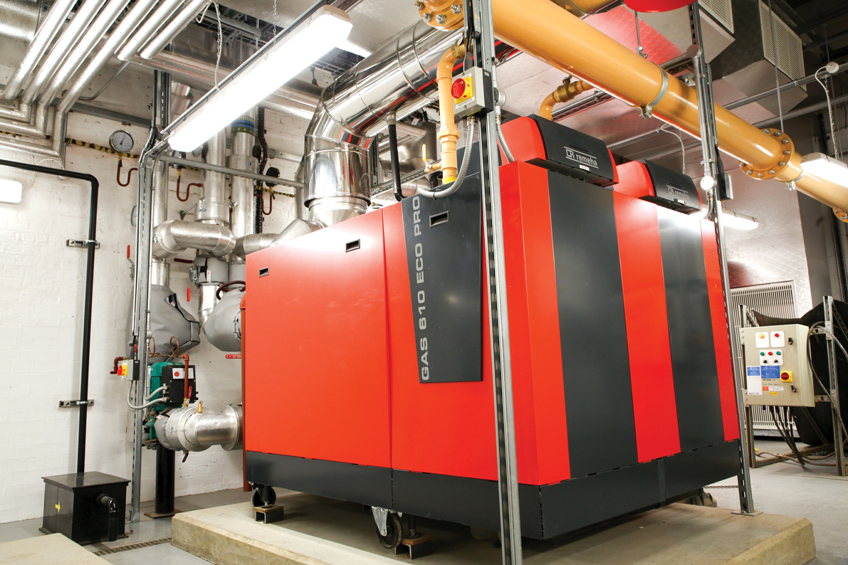
The gas-fired Remeha boilers and pumps enable the new heating system to run concurrently with the existing oil-fired steam boilers, which are housed in a separate plantroom tucked beneath the 1960s extension. The heating mains visible in Dead Man’s Walk connect the new boilers to the existing boiler room.
Two independent heating systems allow the phased switch over of heating as the project progresses, which avoids any disruption to the criminal trials. ‘It is important that there should not be any loss of service to any court, so we’ve designed all of the new systems to be connected to the old ones by using the “hot tap” procedure,’ explains Morgan.
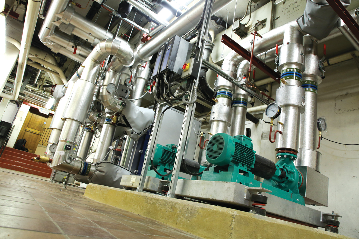
New pumps in the East Wing plantroom
Seven boilers will eventually be installed in the boiler room. To accommodate them in the reclaimed space, Interserve has installed an open-mesh mezzanine floor. Two boilers are currently installed on the mezzanine level, with another two on the lower level. Two more will be installed under Phase 3.
The boilers are not a like-for-like replacement in terms of duty. According to Morgan, the current Netherton oil-fired steam boilers can produce up to 14MW of heat; however, the boilers have been sized to provide 7MW. ‘To meet the calculated heat load with 1.5MW of heat to spare, 5.5MW is needed,’ he says.
‘The City of London Corporation was keen to improve the efficiency and reliability of the heating service, to increase comfort within the building and lower running costs,’ continues Morgan. The boilers were selected for their compact size and high operational efficiencies, and because they can be easily broken down into sections small enough to be manhandled from a lightwell, through a newly created opening for a louvre and into position in the plantroom.
‘We only have one site entrance, which we share with vehicles bringing prisoners in and out of the building. All plant and equipment had to be small enough to be brought in through this entrance, but the maximum size of boilers was defined by the size of the opening to plantroom,’ says Capes.
Ageing equipment in the East Wing plantroom
The boilers are hydraulically separated from the existing heating systems using plate heat exchangers. The existing system is based on two primary circuits – a low-temperature circuit (65°C-45°C) serving the AHU heat batteries and a high-temperature circuit (81°C-72°C), which originally served the radiators and calorifiers, but now serves only the radiators. Domestic hot water is now supplied from newly installed, gas-fired hot-water generators. The high-temperature circuit has had to be retained, however, to provide heat to the existing radiators, which are sized to be fed by the steam system.
The firm is also progressively installing a new building management system (BMS). ‘We add to it as we progress through the various phases,’ says Capes. Only the electrics powering the new plant, and lighting and power in the respective plantrooms, are being replaced. ‘We don’t touch any other electrics,’ he adds. There is also new LV switchgear installed in the existing LV switchroom.
‘We need a lot more pumping energy [even through overall energy use will decrease], so we’ve had to increase the size of the electrical incomer,’ Morgan explains. New low-temperature hot water (LTHW) pumps are needed because the old steam heating system generated sufficient pressure to push heat around the building, whereas the water system has to be pumped. A gas main was also needed to serve the new boilers. ‘We brought the main in from Newgate Street,’ says Capes. ‘It was a hell of a challenge getting it to the site.’
With the heating and hot water plant replacement taken care of in Phase 1, Capes’ next tour stop is the sub-basement AHU plantroom – serving courts 1, 2, 3, 4, 17 and 18 – to see part of the Phase 2 works.
‘The place was awful originally; it was dingy, hot and clammy, because all the existing steam valves were leaking,’ he says. Now the steam system has been removed and new AHUs installed.
‘Originally, courts 2 and 18 were served by a single air handling unit; now, each court has a dedicated unit, so each can be shut down,’ says Capes, standing next to the two shiny new units. These connect to the existing ductwork, which had to cleaned internally overnight to avoid disrupting trials. The junction between old and new is clearly visible at the point where the duct leaves the plantroom. The AHUs have new chilled and LTHW connections. They also have a new humidification system, which was needed because the steam humidifiers were stripped out along with the steam heating. The humidifiers are supplied with water from a new reverse-osmosis water-treatment plant.
In addition to the single AHU serving courts 2 and 18, the single units serving courts 3 and 4, and courts 1 and 17 have been replaced by twin units in this phase of the project. The old plant had to be removed through the boiler house louvre and new plant brought in the same way. ‘To keep all the courts up and running, everything had to be taken out or brought in through the louvre opening in a 16-week programme – which was not a long time, trust me,’ says Capes. ‘The install and maintenance programme rely on two things: logistics and planning.’
Capes leads the way through an airlock into another AHU plantroom (‘it was awful down here’). The airlock is in place because this plant space is effectively an intake plenum for the three replacement AHU units serving the grand hall, ground floor and prisoner ventilation. Fresh air enters the plenum from a sunken passage, close to the end of Dead Man’s Walk, and passes through a bank of filters attached to the rear of the louvre. It is 1pm at the time of the visit, so the courts are at lunch and there is no demand for fresh air (based on CO2 sensing) so the dampers at the rear of the louvre are closed.
Next, it’s off to a new chilled-water pump room, created under Phase 2 to supply the new AHUs.
The chilled-water system was originally arranged as a single circulating pump circuit, to distribute chilled water from the chillers to the AHUs’ cooling coils at a constant volume. Water is circulated constantly through the chillers, irrespective of whether they are operating or not, and through the AHU cooling coils – again irrespective of whether cooling is required.
Under the plant-replacement works, Aecom has reconfigured the chilled water pipework into separate primary and secondary circuits. The primary circuit operates at variable flow determined by the chiller operation, and the secondary circuits operate at variable flow, based on the cooling demand of each AHU cooling coil, differential pressure controls and variable speed inverter drives on the pumps optimise the system performance. Two new pumps have been installed under the Phase 2 works and two more will be installed in each of Phase 3 and Phase 4.
Further down the corridor, Capes enters another AHU plantroom. This contains the existing air handling plant that serves courts 5 and 13, 6 and 14, and the general concourse areas. All of this plant will be replaced under Phase 3 and the steam pipework removed. ‘Everything that you can see in here will get stripped out,’ he says.
The five phases of refurbishment
Phase 1 – Infrastructure and heating
- Create new boiler room in original 1907 boiler room by reinstating louvre openings in the façade to enable access for plant
- Remove oil storage tanks from adjacent room to enlarge plantroom
- Fit new mezzanine platform in the 6m-high space to increase floor area
- Install gas main to the site
- Install the first three of seven Remeha boilers
- Install new HWS calorifiers
- Install pumps to serve new circuits
- Install new LV switchgear
- Install new motor control centre in boiler room
Phase 2 – Courts 2 and 18 (AHU 4); courts 3 and 4 (AHU 5) and courts 1 and 17 (AHU 6)
- Install the fourth boiler
- Install new humidifier water-treatment plant
- Install new heating and chilled-water mains to plantroom
- With courts 2 and 18 out of use, remove old air handling unit (AHU 04) and replace with new
- Clean existing ductwork
- Connect new AHU to existing ductwork and new heating and chilled water mains
- Undertake a similar procedure for courts 3 and 4, followed by 1 and 7
- Remove and replace AHUs 7 and 8 serving the general circulation areas, and clean ductwork
- Remove and replace AHU 9, serving the prisoner areas and clean ductwork
Phase 3 – South wing basement, courts 5 and 13, and courts 6 and 14, with court 5 out of use
- Install temporary duct between concourse supply and court 13
- Remove and replace AHU and connect to new heating and chilled water mains
- Clean ductwork to court 5 and connect to new AHU
- With court 13 out of use, clean ductwork and connect to new AHU
- Undertake a similar procedure for courts 6 and 14
Phase 4 – South wing 6th floor, courts 7 and 15, and courts 9 and 10, and south wing 6th floor, courts 8 and 16, 11 and 12
- Strip out six AHUs, extract fans and associated pipework, and replace
- Install the last two boilers
Phase 5 – Chillers and cooling towers
- Strip out and replace, in a sequenced manner, chillers and cooling towers
The works to these courts have had to be meticulously planned. ‘For this phase, we can only shut down one court at a time, even though the plant currently serves two courts,’ Capes explains.
The solution is to replace the AHU serving the general concourse areas first and then take a temporary supply from that unit to court 13 while the AHU serving court 5 is replaced. Interserve will do the same for courts 6 and 14.
‘This is not a big phase – it only lasts for 12 months – but, logistically, it’s a lot harder,’ says Capes, whose tour then passes through a space called the undercroft (‘an absolute mess’). This has been cleaned out and now contains heating mains, installed under Phase 2 ready for use in Phase 3.
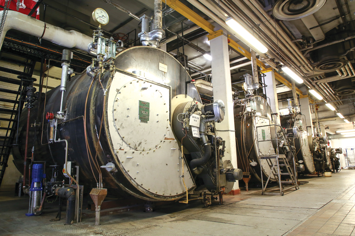
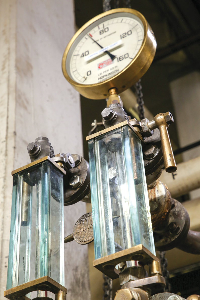
The tour finishes with a quick look at the existing East End plantroom (‘bloody hot’), which houses the four giant Netherton oil-fired steam boilers that have successfully provided the courts with heat and hot water for 50 years. It has become increasingly difficult to source spare parts for these monsters, so the boilers will be removed in a later phase.
Also in the plantroom is an old plan chest, its top heaped high with thumbed blueprints, many dating from the original 1907 installation. It’s a stark contrast with the modern BIM model being used to help the complex refurbishment be delivered while criminal cases are still being tried.