The successful integration of a biomass boiler with fossil-fuelled boilers requires an in-depth understanding – informed by measurement and calculation – of the performance and shortcomings of the system into which it is being installed. Simply connecting a biomass boiler in parallel with a conventional system can result in flow-temperature dilution, flow sharing, and power-output limiting. Any one of these problems is often accompanied by one or both of the others, and only in a properly understood, designed and balanced system can they all be avoided.
Flow-temperature dilution
The problems of flow-temperature dilution were explained in GIR40: Heating systems and their control1 (see Figure 5), and extended by me in ‘Talking Headers’ (CIBSE Journal, February 2014)2. It occurs when the bypass flow from offline boilers mixes with the output from firing boilers, and when the total flowrate on the load circuits is greater than the boiler primary loop flowrate. For a complete description, refer to these publications.
Flow sharing
When only fossil-fuelled boilers are installed, the individual contribution from each boiler is of no concern to the end user. When a biomass boiler is included, however, its maximum output is required for financial and carbon-reduction reasons.
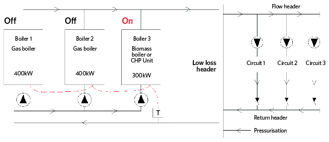
Figure 1: Hybrid boilerhouse with only biomass boiler firing
Many biomass boilers have been added to existing systems, and Figure 1 shows a typical schematic in which only the biomass boiler is firing and supplying the full load. When a fossil-fuelled boiler is also firing, however, the load will be shared between the active boilers, in the ratio of the flowrates through the boilers. In this case, the 400kW boiler will supply 57% of the load – 400kW/(400kW+300kW) – and the biomass boiler 43% (see Figure 2).
However, if the fossil-fuelled boilers operate at 11°C temperature differential (ΔT) on a load system designed to operate at 11°C ΔT while the biomass boiler is set to operate at 20°C ΔT – a not infrequent finding – the biomass contribution will reduce to 29%. Temperature dilution will also occur on this circuit if the total primary flowrate is less than the total secondary flowrate. The simple remedy is to connect the biomass boiler in series injection with the system return, as detailed in Figure 3.
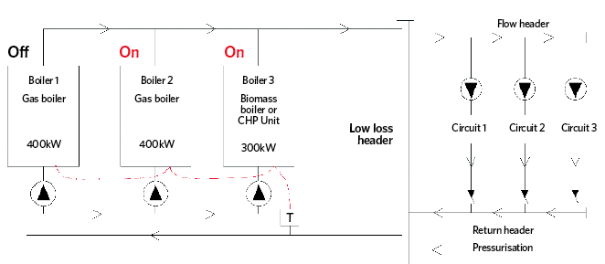
Figure 2: Fossil-fuelled and biomass boilers both firing
Flow sharing is the most common reason biomass boilers fail to supply their potential output, and was found in 50% of the systems surveyed. The worst case was a 2.1MW boiler supplying only 42% of its output, with the consequential loss of more than £30,000 per year in Renewable Heat Incentive (RHI) income.
Power-output limiting
The most common symptom of power-output limiting is that a boiler is unable to supply its full output. Taking measurements of flowrates and temperatures, and then doing a simple mathematical analysis, is the only certain way to identify when power-output limiting is occurring.
Many biomass systems have been abandoned, while others continue to underperform because the reasons for this are poorly understood
The example below is for a system in which the biomass boiler has never – and will never – achieve its full output. It is important to understand the load system ΔT always determines the boiler ΔT. The problem arises when the maximum load ΔT is less than the design ΔT of the biomass circuit. On this system (Figure 4), the lowest biomass design ΔT achievable is 14.2°C3, with the pump at maximum speed, whereas the maximum load ΔT is 8.5°C. This limits the boiler output to 8.5/14.2 = 60%, or 120kW. Loads above this value are met by LPG boilers, resulting in an under-used biomass boiler.
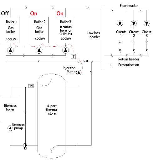
Figure 3: Biomass boiler connected in series injection with the system return
The solution is to increase the flowrate of the biomass boiler pump – which requires a pump upgrade – to achieve a minimum flowrate of 5.63kg/s at a design ΔT of 8.5°C. However, the issue with many systems is that the load circuits never return their design ΔT. There are many possible reasons for this, but a solution to rectify a load ΔT that is too low may be more complex and costly than pump replacement.
Boilerhouse modelling
The key to identifying and understanding these problems is to measure and model. Measurement of temperatures throughout a system is straightforward, but measurement of flowrates at all key points is equally important. These need to be repeated for each combination of boilers and load circuits that are likely to be used. Well-specified systems will have orifice plates and commissioning sets that allow the direct measurement of flowrates. Where RHI heat meters are installed, some of the flowrate data can be read directly and, failing this, clamp-on flow meters can be used.

Figure 4: Biomass system with data showing how power output limiting can occur
My approach is to draw a schematic of the system in Excel and populate it with data at each point of the system. Temperatures and flowrates are then calculated at each mixing node – that is, at the biomass boiler back-end valve and the flow-mixing valve in the simple example in Figure 5. This approach allows the examination of different operating scenarios, from which the problems of temperature dilution, flow sharing and power-output limiting can be identified and quantified. Using the model, input parameters can be varied to determine the system changes required to eliminate the problems identified. This methodology has been applied on boilerhouses of up to 8MW containing multiple boilers – including biomass – and with many load circuits.
Practicalities of system remediation
My article in the November 2017 Journal covered flue upgrading and replacement – which may or may not be possible, depending on system geometry and planning considerations. Remediation of systems with hydronic configuration and sizing problems is usually more straightforward.
The worst case was a 2.1MW boiler supplying only 42% of its output, with the consequential loss of more than £30,000 per year in RHI income
For underperforming parallel-connected systems, pipework will have to be changed to convert the system to series injection, and an algorithm will be required to control the rate of heat injection into the return header. Pump upgrades may also be needed, as will system recommissioning, based on outputs from the boilerhouse model. When boiler seasonal efficiency is low – and/or the boiler is oversized significantly– a better option could be to install a smaller boiler.
Covering remediation costs
Many biomass systems have been abandoned, while others continue to underperform because the reasons for their under- or non-performance are poorly understood – plus, there is a lack of funding for rectification work. Several options are available for biomass-system remediation, including a:
- Paid-for analysis and repair service, offered by many companies, which may not be suitable when capital funding is required
- System-replacement agreement to provide a more appropriate boiler, with ongoing costs going into an energy service company (ESCO), and with possible RHI transfer to a finance company
- Biomass RHI transfer arrangement, to allow re-financing of a boiler by transferring boiler ownership and the RHI to a finance company.
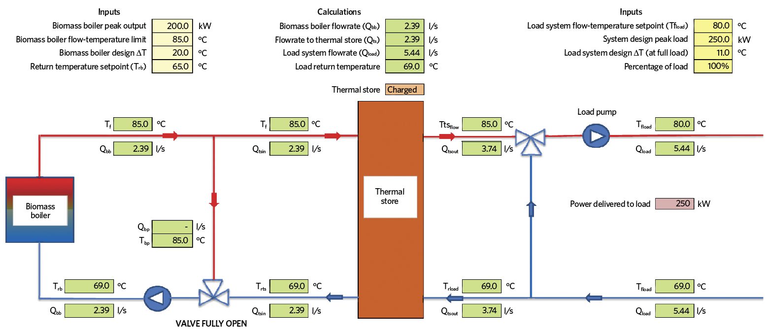
Figure 5: Simple boilerhouse model implemented in Excel
Boiler maintenance and fuel would be included in the last two options. Alternatively, an unwanted boiler could be bought with RHI transfer for re-use elsewhere, attracting a higher second-hand value than the boiler alone.
Summary
This article, and my previous one, have described the findings of detailed surveys of biomass boiler installations, the key reasons for biomass boiler underperformance, and the measures required to rectify significant deficiencies. Improvements to flues, thermal storage, and hydronic arrangements will address many of the issues identified.
The final article in this series will focus on the findings of surveys of conventional boilerhouses, the results of system hydronic analyses, and the measures implemented to correct the significant defects and shortcomings identified.
Notes
- Heating systems and their control, General information report 40.
- Talking headers, CIBSE Journal, February 2014.
- 14.2°C = 200kW/(4.18kJ/kgK x 3.37kg/s)
■ David Palmer is a director of the Campbell Palmer Partnership and principal author of CIBSE AM15: Biomass heating