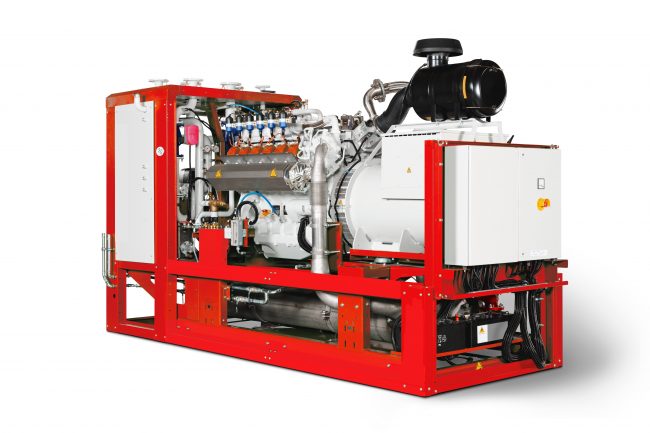
When integrating combined heat and power (CHP) into new-build and retrofit projects, the most common approach is to use it in series with boilers. This offers a consistent way for the CHP to see load, working as a preheat for boilers when demand is beyond the CHP’s reach. It can also mitigate the risk of a high return being fed back to the CHP.
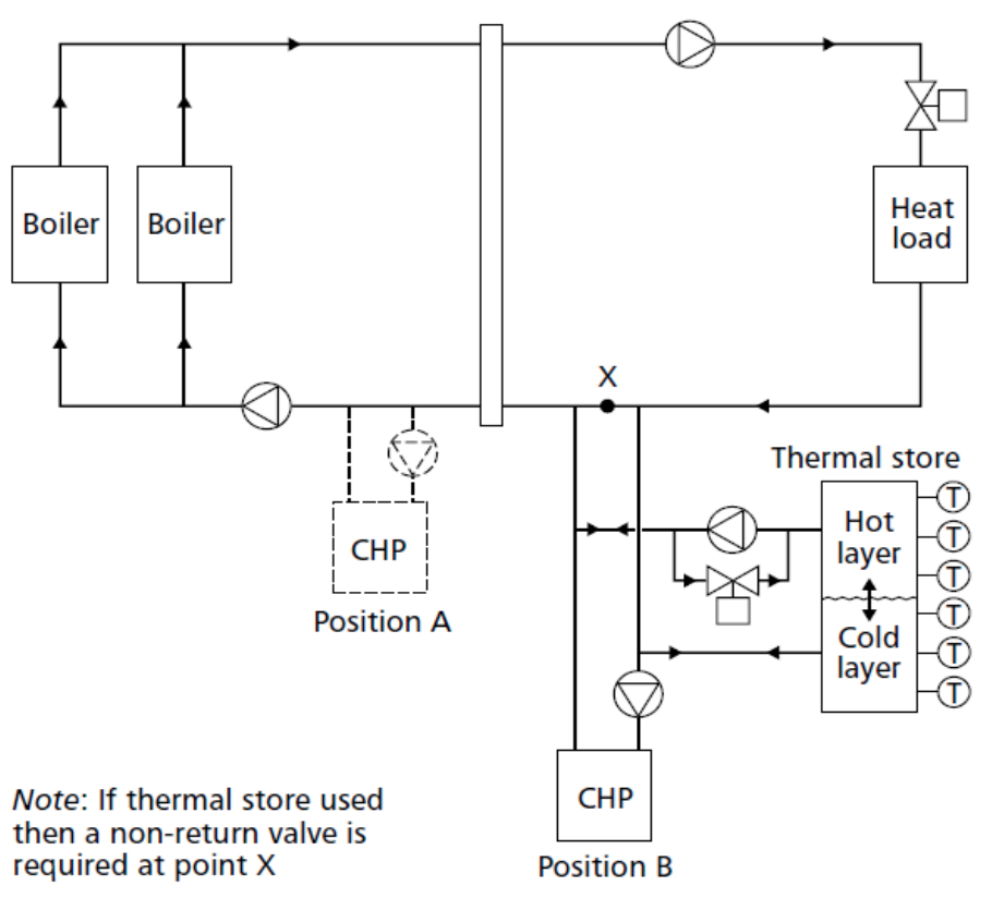
Figure 1: CHP in series (CIBSE Applications Manual AM12 guide)
However, during certain load conditions, a series connection can remove the boilers’ ability to condense and decrease their efficiency.
We can understand this better with a node-by-node analysis of a typical CHP and boiler setup with the CHP sized at approximately 10% of an assumed 400kW peak load (see Figure 2).
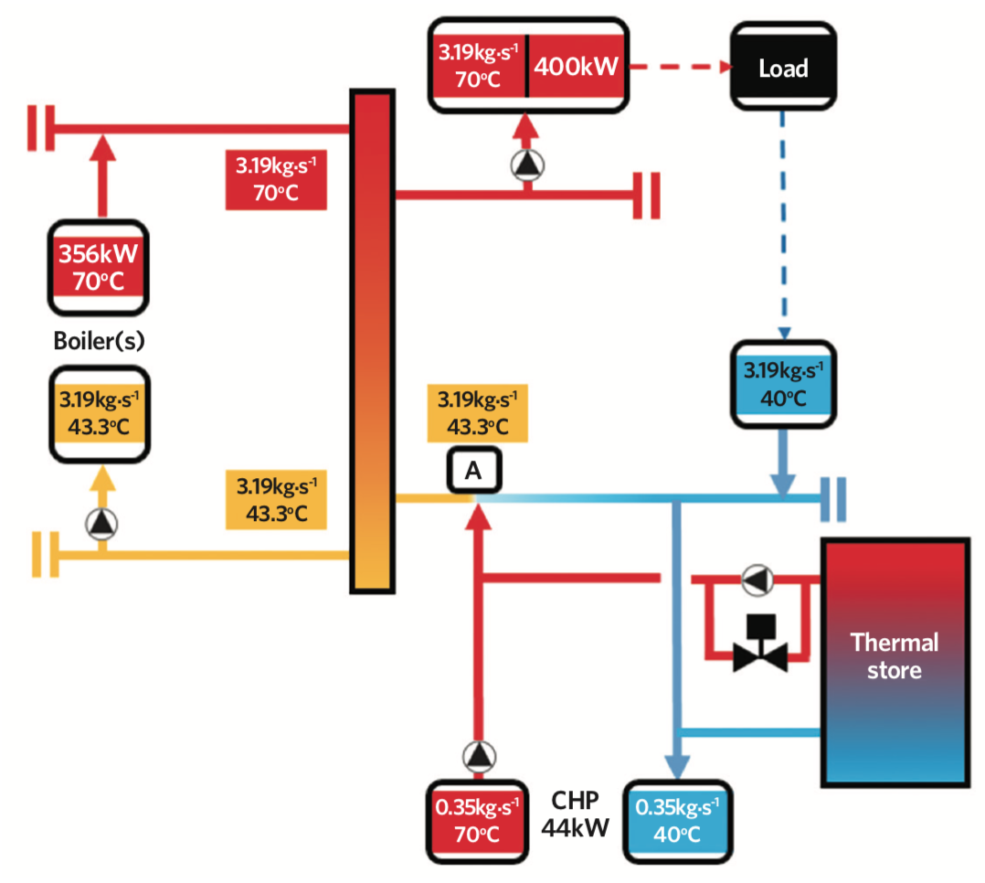
Figure 2: CHP in series – full load
This design assumes a flow of 70°C and return of 40°C, which is within the condensing bracket for both boilers and CHP (where the CHP can condense). As the CHP sees a portion of 400kW load, the 70°C flow from the CHP will increase the boiler return water temperature to 43.3°C at node A.
The smaller temperature difference, or ΔT, reduces the load on the gas boilers, decreasing the firing rate and cutting gas consumption.
However, the rise in return water from 40°C to 43.3°C will also affect the boilers’ condensing operation, lowering overall boiler efficiency by approximately 2% as shown in Figure 3.
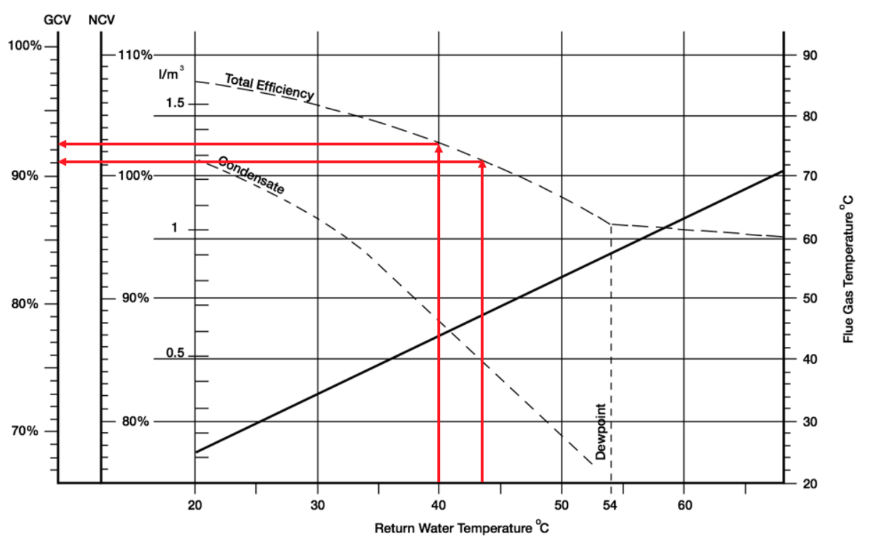
Figure 3: Boiler efficiency – 43°C v 40°C return
Using the same baseline conditions as in Figure 2, in Figure 4 we can see an assumed part load of 88kW. This example shows the boilers receiving return water at 55°C generated at node A.
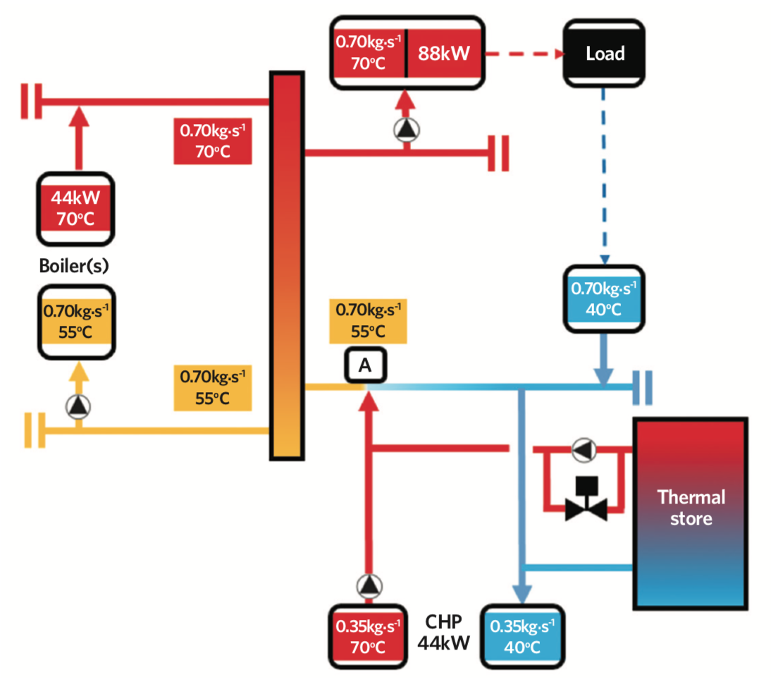
Figure 4: CHP in series – part load
The higher temperature restricts the boilers’ ability to fully condense, reducing efficiency by up to 7% (see Figure 5).
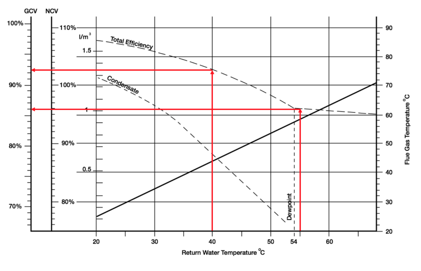
Figure 5: Boiler efficiency – 55°C return v 40°C return
In some cases, a marginal lift of this return temperature at full load can be accepted as the CHP mass flow rate is small compared to the system return volume. However, during part load, the lift in temperature could drastically impact the efficiency of the major source of heat.
Condensing your design
As a CHP unit only delivers savings when it’s running, carrying out a feasibility study and checking the heat and power demand profiles is critical, as is ensuring absolute full use of heat without dumping into the atmosphere.
However, for condensing arrangements, the boilers must also be able to operate in condensing mode. This cannot be achieved practically or fully in preheat-style series designs, as a result of return water blending. For this, we would require a modified parallel arrangement.
By introducing this, we enable hydronic separation between different heat generation devices (see Figures 6 and 7) and separate the heat load from generation via a low loss header with flow and return headers attached.
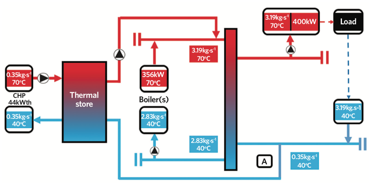
Figure 6: CHP modified parallel arrangement – full load
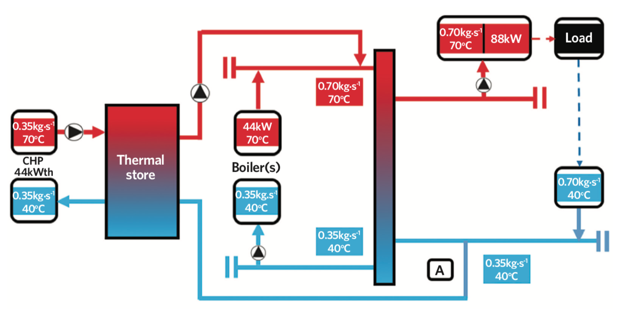
Figure 7: CHP modified parallel arrangement – part load
Applying the same nodal analysis as before (in Figures 2 and 4), under the same system conditions, there is no preheat to the return water back to the boilers. Both the CHP and boilers are receiving 40°C return and maximising the system efficiency via condensing operation.
During times where boiler flow is not removed by the load and forward flow occurs, it will not interact with the CHP return. The boiler ΔT will reduce but the CHP will continue to condense.
However, the main advantage is that at part-load conditions, the additional heat required by the boiler to meet system demands is fully condensing, giving maximum efficiency.
It is important to note that the system philosophy must be qualified prior to application on new and existing systems. As a modified parallel arrangement assumes variable flow on both primary and secondary, with close control load ΔT, older, non-condensing systems with retrofitted CHP will benefit more from a series arrangement. Careful analysis of nodes, temperatures and flow rates is necessary to understand fully where the CHP will best fit to improve all heat-generation efficiency.
Thermal stores and buffers
We can also explore the full benefits of a thermal store and utilise its stored energy to deliver more heat for longer, a topic we will expand on in our next feature.
Both two-port and four-port thermal stores offer a means of releasing heat stored via charge from the CHP. In a four-pipe configuration (see Figure 8), the CHP flow constantly interfaces with the thermal mass in the tank, while a two-pipe configuration (see Figure 9) allows the CHP to bypass the tank straight to load.
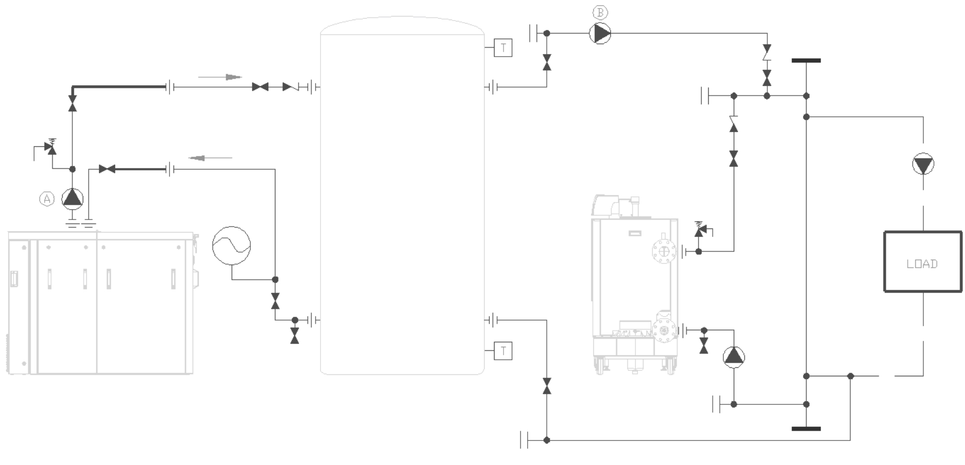
Figure 8: Simplified CHP/boiler design – four-port thermal store
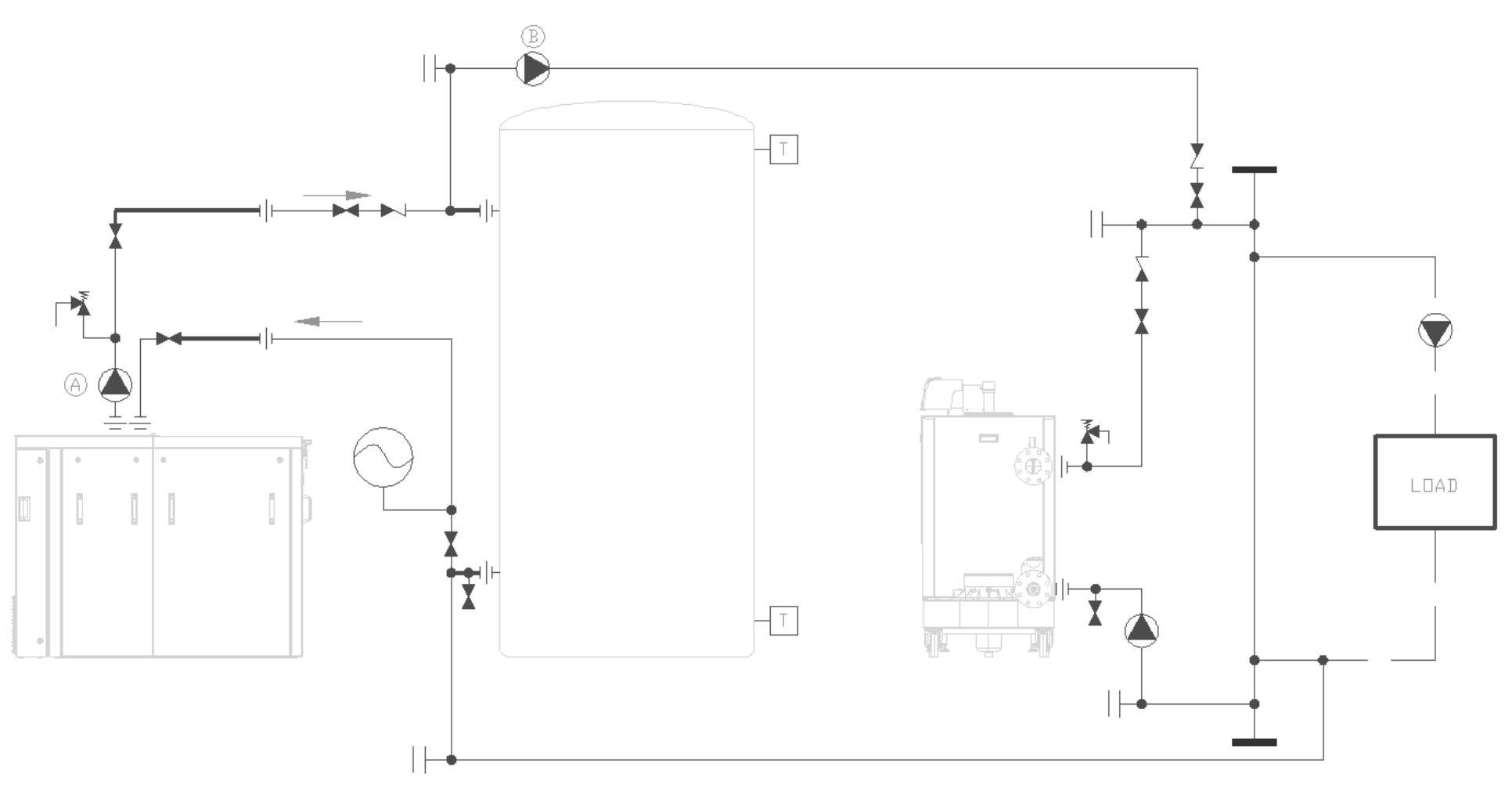
Figure 9: Simplified CHP/boiler design – two-port thermal store
In both cases, the discharge pump (B) is able to control actively if the tank is charging, discharging or in equilibrium. It does this by adjusting flow rate while observing temperatures within the tank as the thermocline moves.
Most manufacturers will recommend a four-pipe configuration as the heat source always interacts with the thermal store, an approach which works best under steady-state loads. This also adds another layer of protection for the CHP and allows for more flexibility with tank pipework. However, where applicable, a two-pipe configuration can be utilised to allow direct online flow for the CHP at the expense of a slightly more constrained installation.
In both examples, this methodology allows for full condensing operation of both the CHP and the boilers throughout the entire load range without sacrificing the efficiency of either unit. While outside the scope of this discourse, full consideration of electrical use is crucial when developing any CHP solution. Key understanding of base load and exporting clauses is an absolute requirement.
Check list for modified parallel arrangement
This article describes how we approach CHP and boiler design for optimal efficiency, but it is important that the following factors are considered prior to application:
- Is the overall system condensing?
- Does the system have a fixed or variable flow rate?
- Are the boilers condensing or non-condensing?
- Do the boilers have fixed or variable speed pumps and what controls them?
Understanding the system fully before applying any solution is vital. While there is no ‘one size fits all’ solution with CHP, applying the right methods at the right time will set you up for project success.
In our follow-up feature, we will explore thermal store sizing and controls, providing more detailed schematics and key examples with results.
About the author
Ryan Kirkwood is specification manager at Remeha. Part two of this series, published in spring 2020, will explore thermal store sizing and controls