Interior lighting design by BuroHappold for the Museum of the Future in Dubai
BIM has become a buzzword over the past few years, and most designers, contractors and manufacturers are talking about digital engineering in one form or another – but what does it really mean and how does it affect the lighting sector?
I would like to try to unpack the reasons why we all should be looking seriously at digital engineering as a method to improve efficiency and product, no matter which part of the industry your company operates in.
For my own sanity, I like to differentiate between BIM Level 2 – the government-mandated process – and BIM, which I tend to refer to as digital engineering. It is more about using technology to do the boring stuff better, freeing us up to do the interesting and artistic things.
There have been endless articles about BIM Level 2, most of which extol its virtues as a new technology and a fresh way of collaborating. Well, it’s not that new, actually; one of the first construction projects to use Level 2 concepts was Heathrow Terminal 5, the design of which began in 1989 and which was completed in 2008.
These concepts have now been codified and standardised through British and international standards, of which I won’t go into detail. They are all free to download from the BSI website, and the CIBSE Digital Engineering series of publications explain in greater depth. The nub of what these processes are trying to achieve is the simple, seamless and painless exchange of data.
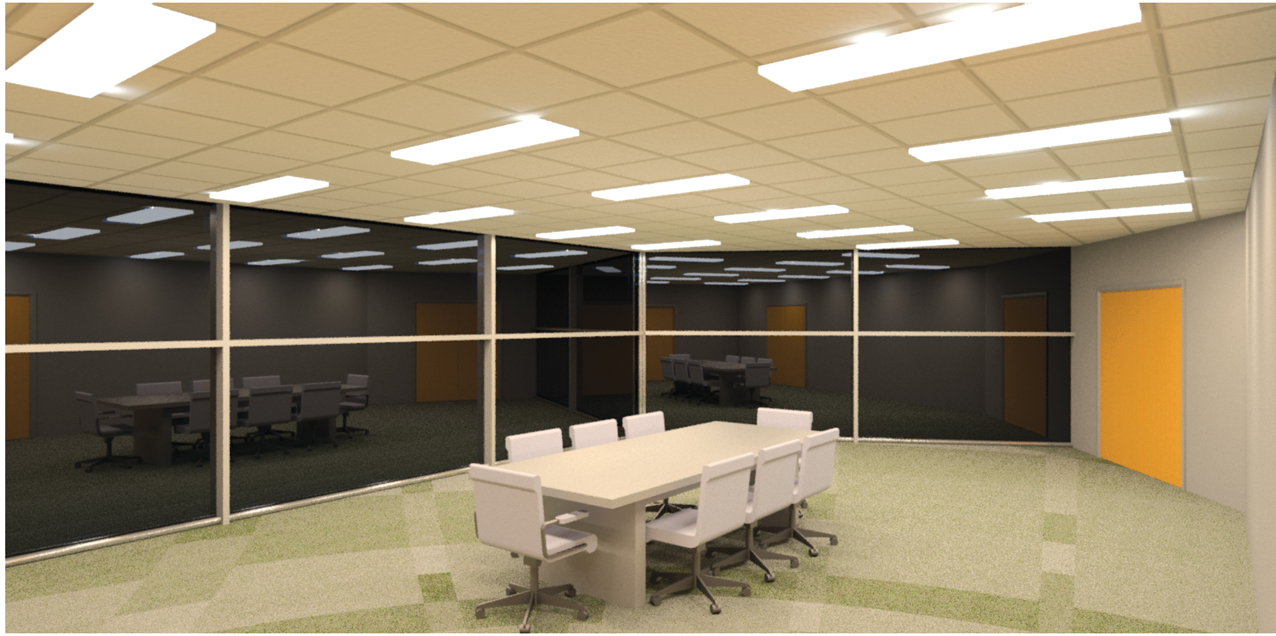
Daylight visual, showing the client how the rendered layout looks
It turns out that the construction industry is really rather poor at exchanging information – and this is the root cause of many errors, overruns and budget-busting costs. So, let’s all play nice and share our data in structured forms! The world will be a better and happier place, with construction projects that come in on time and budget, and facilities managers who inherit a complete data set that populates their CAFM systems.
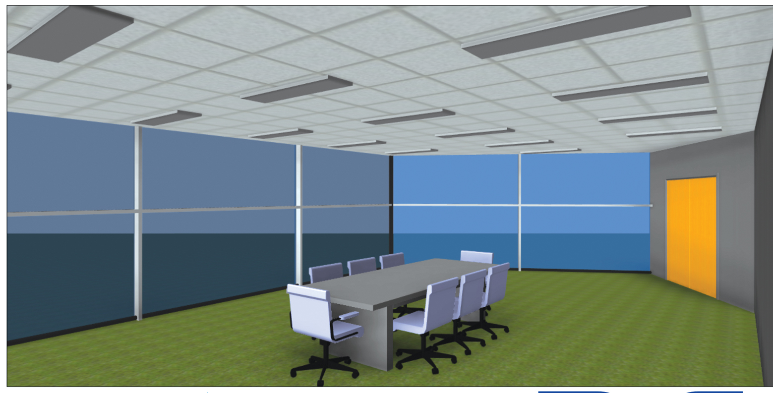
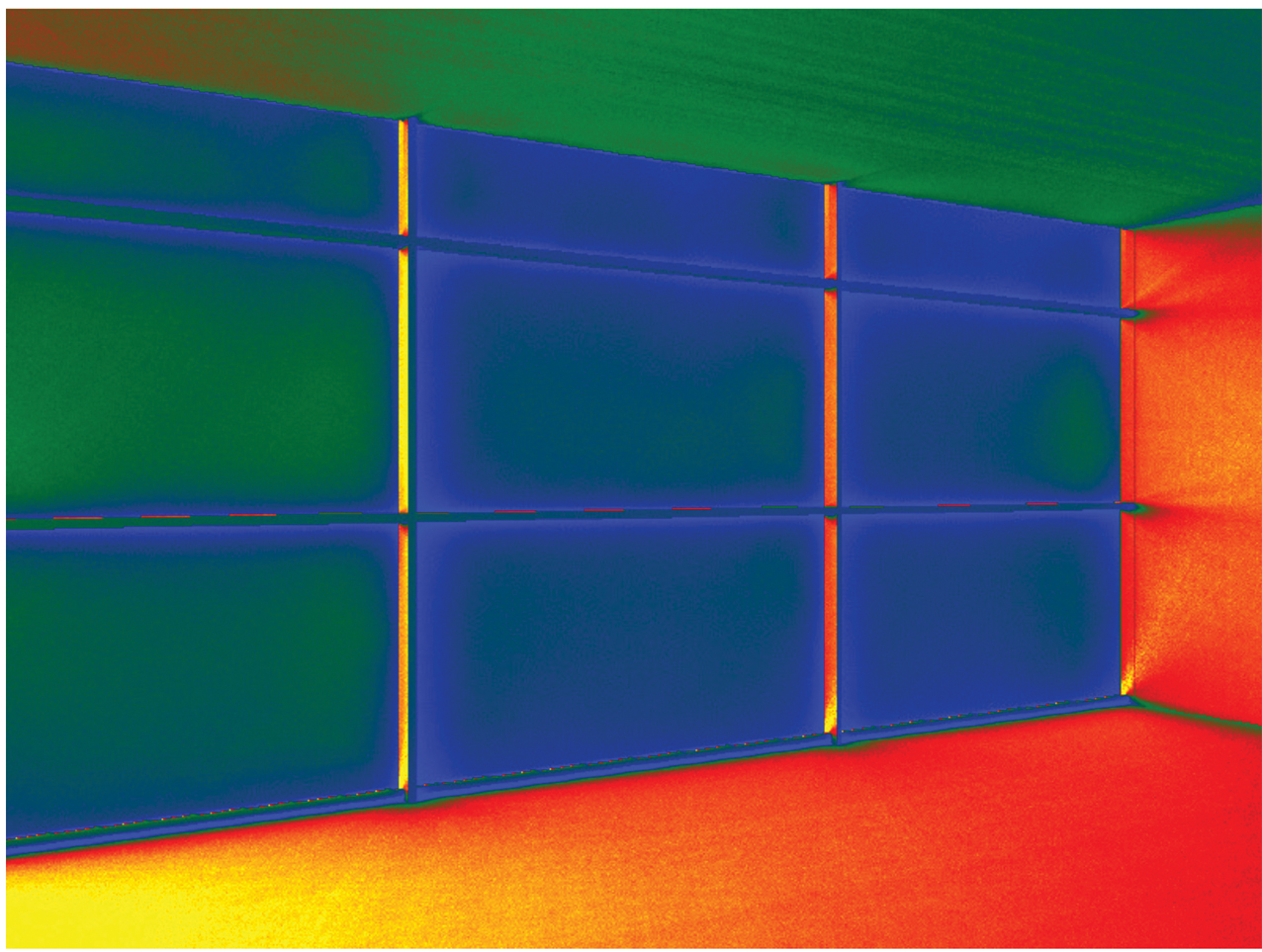
A quick daylight analysis
Digital engineering is the stuff that gets me out of bed in the morning. This is the application of technologies we already have available to do the meat and potatoes work that seems to take up most of our working lives. I’m more a quinoa and kale kind of guy, so I want that stuff to just take care of itself. Can it? Well no, not quite, but we can take a lot of the drudge out of it.
Daylight visual, showing the layout in a simple cartoon form
Let’s take luminaire schedules for a start. Not that much fun to create, and less fun to keep up to date as the design progresses. It’s easy to miss something and – if you are trying to keep count of the number of each type of luminaire – you can spend your entire day counting and recounting.
This is something we can easily automate. If you are using a modelling package to generate your designs, the luminaire schedule is just another view of the same data, so it will update automatically. Data can be fed into the schedule by using information supplied in a structured format such as a CIBSE Product Data Template (PDT). This contains industry-agreed parameters and uses CIBSE BIMHawk technology – free to use for everyone – to feed it through into design platforms.
So, what other tedious tasks can the machine do for us? How about circuiting up some luminaires? Drawing little curly lines from one luminaire to the next, room after room – then adding the circuit references – takes time, is prone to error, and has a fun quotient of 0.001.
In our modelling platform, we can select the fittings that are to share a circuit and, if the objects are configured correctly, we can create a power circuit for them, going back to a distribution board. Or we can collect them up for a lighting control module. The software will assign them to a way on the board and generate the lines to create the circuits on the drawings automatically.
I like to use a filter on the view to show the phase to which each circuit is assigned, assuming our distribution board is three-phase with single-phase circuits. I’m a bit of a traditionalist with phases, so I use red, yellow and blue to highlight which phase is assigned to which circuit.
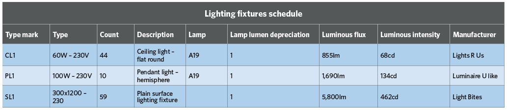
Grand total: 113. If you are using a modelling package to generate your designs, then the luminaire schedule is just another view of the same data, so it will update automatically
The diagram below shows that each circuit in the space is assigned to a different phase, and that I’ve called my distribution board DB1/Lgts. Maybe I don’t want that – maybe I want to have a single phase in the space (safety first) and to call my distribution board DB1/LTG. I can do that in a different view of the same data; I have a distribution board schedule as a view of my project so – if I make changes there – it will also change on my drawings.
This is pretty straightforward to do, and means I’ve got my distribution board schedule as well – which is another of my deliverables done by dropping some luminaires into the room, with a couple of clicks to connect them up.
That’s why digital engineering gets me up in the morning – solving all those issues that have governed my working day for the past few decades: drawing the circuit lines, typing out the luminaire and distribution-board schedules, and adding circuit references manually.
What other tasks can we automate? The honest answer is, I don’t know. It depends how smart we want to be with this. There is no point creating all these clever processes if they are not going to make us more efficient, so it depends on what you – as a lighting designer – want to automate, and how easy that will be to execute.
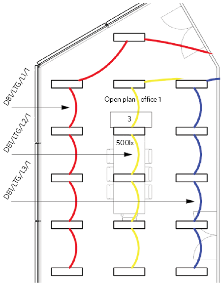
Distribution board DB1/Lgts, with each circuit in the space assigned to a different phase
Some things I have tried and succeeded at in the past include quick daylight analysis, though this is not as thorough as calculating properly. All the daylighting visuals (above) are different views of the same data. The luminaires used in this example are generic, but are using real .IES files to generate the rendering and the illumination calculations. The rendered layout visual is a deliberately uncomplicated design, to demonstrate the principles that can be applied to any project, no matter how complex.
The purpose of this is to show that digital engineering is all about making your day job easier; taking away – or reducing to a minimum – all the tasks that take time and can be done by machines. This then allows the designer to focus on the things that really matter, such as the experience of the space, the quality of light, and getting a good system designed to a tight budget.
Whatever the parameters, let’s allow the designers to design – and the software should be able to take care of the rest.
■ Carl Collins is digital engineering consultant at CIBSE. He is the guest speaker on digital engineering and lighting for SLL’s latest Lighting Knowledge Series: Light Bytes.