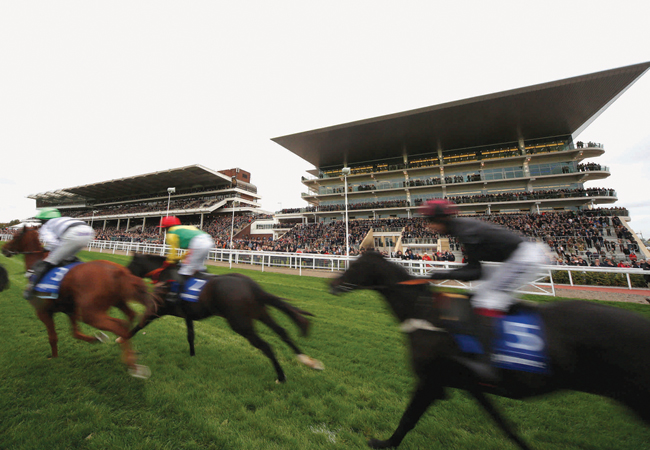
The new grandstand makes an impressive backdrop to racing at Cheltenham
Cheltenham Racecourse is among the most famous in the world, and home to one of the most prestigious events on the racing calendar – this month’s Cheltenham Festival.
The event hosts the Cheltenham Gold Cup, which attracts the best horses from the UK and Ireland, and some of the biggest crowds in racing, including thousands from across the Irish Sea. The Festival is renowned for the ‘Cheltenham Roar’ – the eruption of crowd noise when the starter first raises the tapes.
The atmosphere will be even more intense this year after the opening of a new 6,000-capacity grandstand last November.
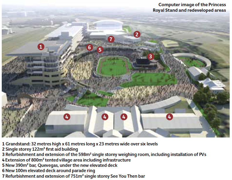
Designed by architect Roberts Limbrick, the Princess Royal Stand is part of a £45m redevelopment of the racecourse – owned by Jockey Club Racecourses (JCR) – which includes a major renewal of the area around the grandstand and parade ring.
Building services consultant Baileygomm designed the services for the new grandstand and ancillary buildings, and redesigned the services infrastructure across the site.
JCR demanded a services strategy that allows the grandstand to be used all year round – not just on the 16 racing days. This presented a significant challenge for Baileygomm. It had to design a system that allowed lighting, heating and cooling to be controlled zonally, so spaces such as the royal box could be hired out for weddings, exhibitions and other events.
Project team
Client: Jockey Club Racecourses
Building services: Baileygomm
Architect: Roberts Limbrick
Structural engineers: Furness Partnership
Landscape architects: Illman Young
Principal contractor: Kier Construction
Project manager: Arcadis
Mechanical and electrical contractor: CF Roberts
The complexity of the services meant Baileygomm had to redesign the electrical infrastructure from scratch. The existing mass of wires and cable would not cope with the extensive power and telecoms service requirements for the new grandstand.
Project director Ian Bailey FCIBSE split the work into four design elements – mechanical services, high-voltage (HV) and low-voltage (LV) power distribution, lighting, and IT/racing technology. Each had a lead engineer, three of whom explain the challenges here.
The project was completed in October 2015 and Baileygomm will benchmark energy performance over the next few years. The stand cements Cheltenham’s reputation as one of the world’s best racecourses and the design enables the building to be used all year round, so non-race goers can take advantage of the fantastic new facility.
Mechanical services
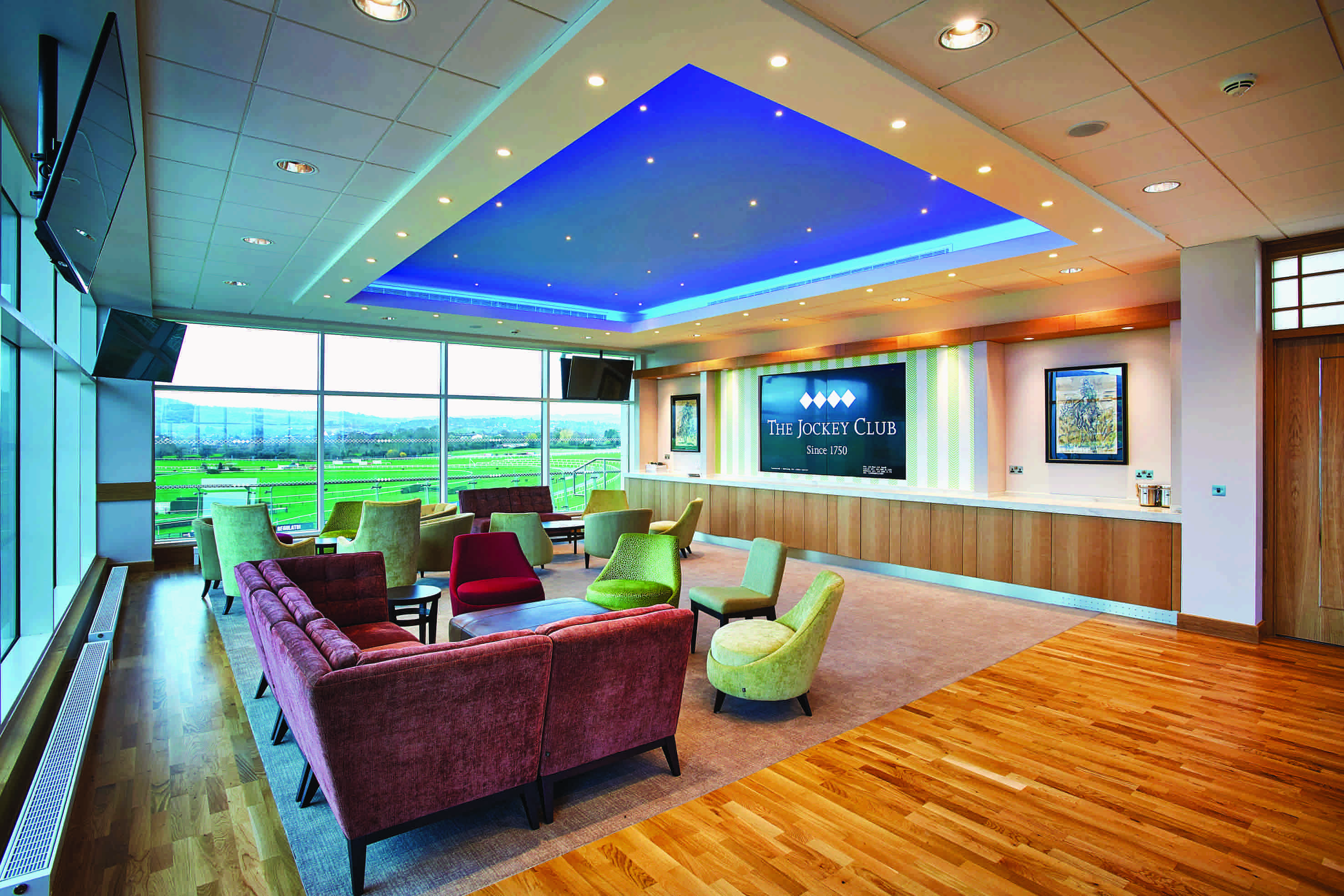
Senior engineer, Simon Roberts-Eagles, says one of the main challenges on the scheme was usage patterns. For 340 days, many of the buildings are vacant because the racecourse is only used for winter racing. However, some areas – such as the top-floor restaurant, the royal box and the main, ground-floor bar area – can be hired for events. So the building needed to be flexible in its operation, but with the minimum of plant, to ensure capital costs were not inflated.
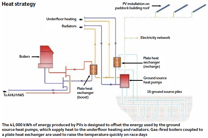
When there are no events, the building will be in setback mode, by reducing building temperature and therefore energy demand. After reviewing the available heat sources – and because of the low setback plant load – the decision was made to use a ground source heat pump (GSHP). This is sized to meet 90% of the annual heating demand and 16 x 125m-deep boreholes were installed under the members’ lawn.
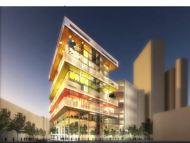
Rooms in the stand can be hired on non-race days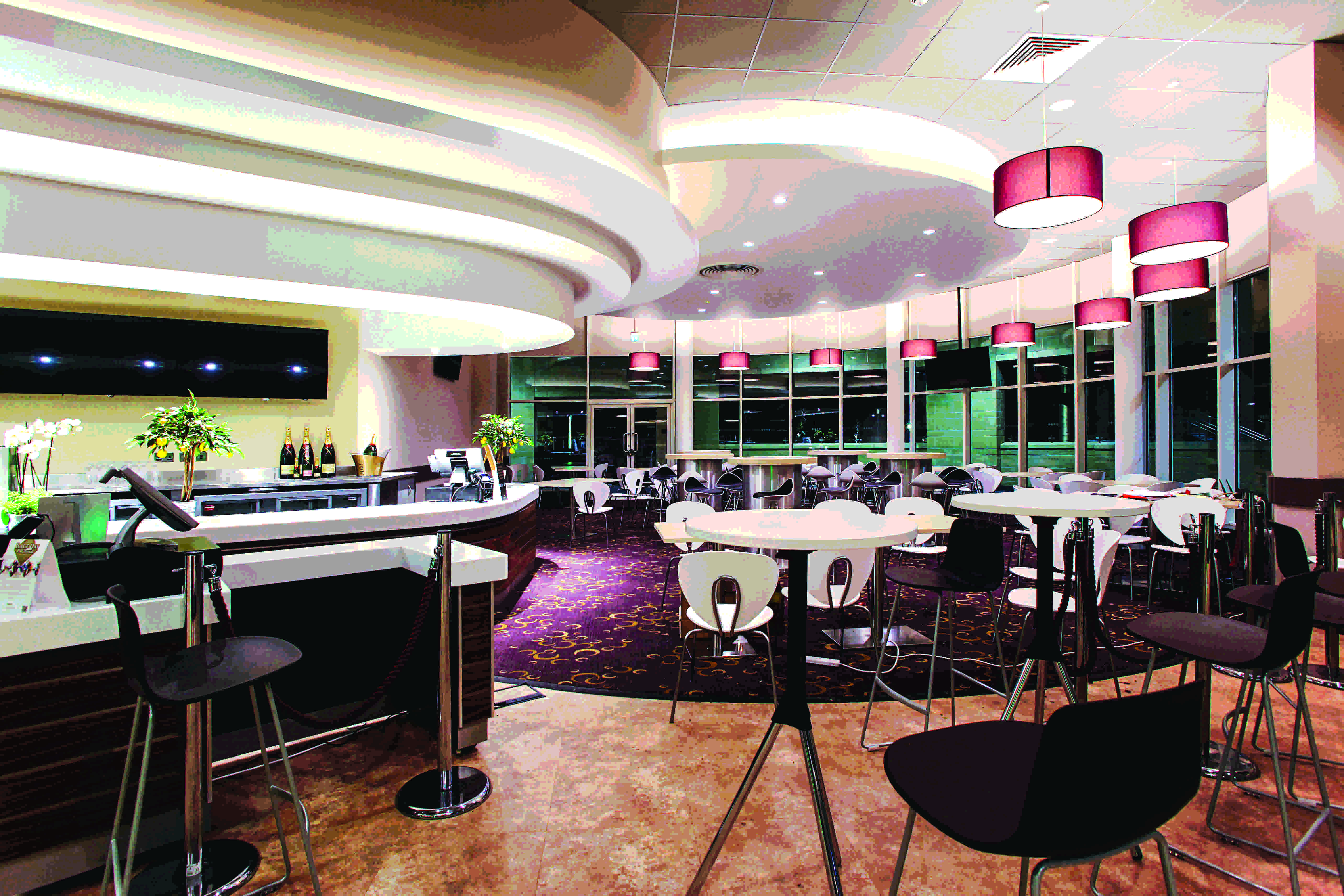
The 1,500m² ground-floor bar area is heated by a wet underfloor heating system. This removes the need to run air handling units (AHUs) to heat the space while unoccupied. As underfloor heating uses low flow and return temperatures, we were able to connect the GSHP directly to the underfloor system. The rest of the building is heated by radiators, via the GSHP.
However, to allow fast heat-up of the building before race day, the radiator system is also coupled to a heat exchanger fed from the boiler system. By feeding the radiators from the boiler, the flow and return temperatures can be raised to increase the heat output of radiators. The removal of the radiators from the GSHP circuit allows the GSHP to feed only the bar area, allowing a greater heat output from the underfloor heating.
To improve the coefficient of performance (COP) of the GSHP, the heating system is linked to the ground source loop via a plate heat exchanger. Heat is then drawn from the large open space in the summer and pumped around the borehole system, to recharge the ground.
To increase the overall efficiency of the project, photovoltaics (PVs) were installed on the weighing-room roof. These helped the grandstand comply with Part L, and will generate approximately 41,000 kWh of energy and offset 21,000 kg CO2 per year. They are designed to offset all of the energy and CO2 consumed and produced by the GSHP.
In total, four AHUs serve the grandstand, delivering around 50m3/s when the building is being fully used, with air volume driven by occupancy. A system of shut-off dampers is located on each floor so that individual areas can be ‘switched on’.
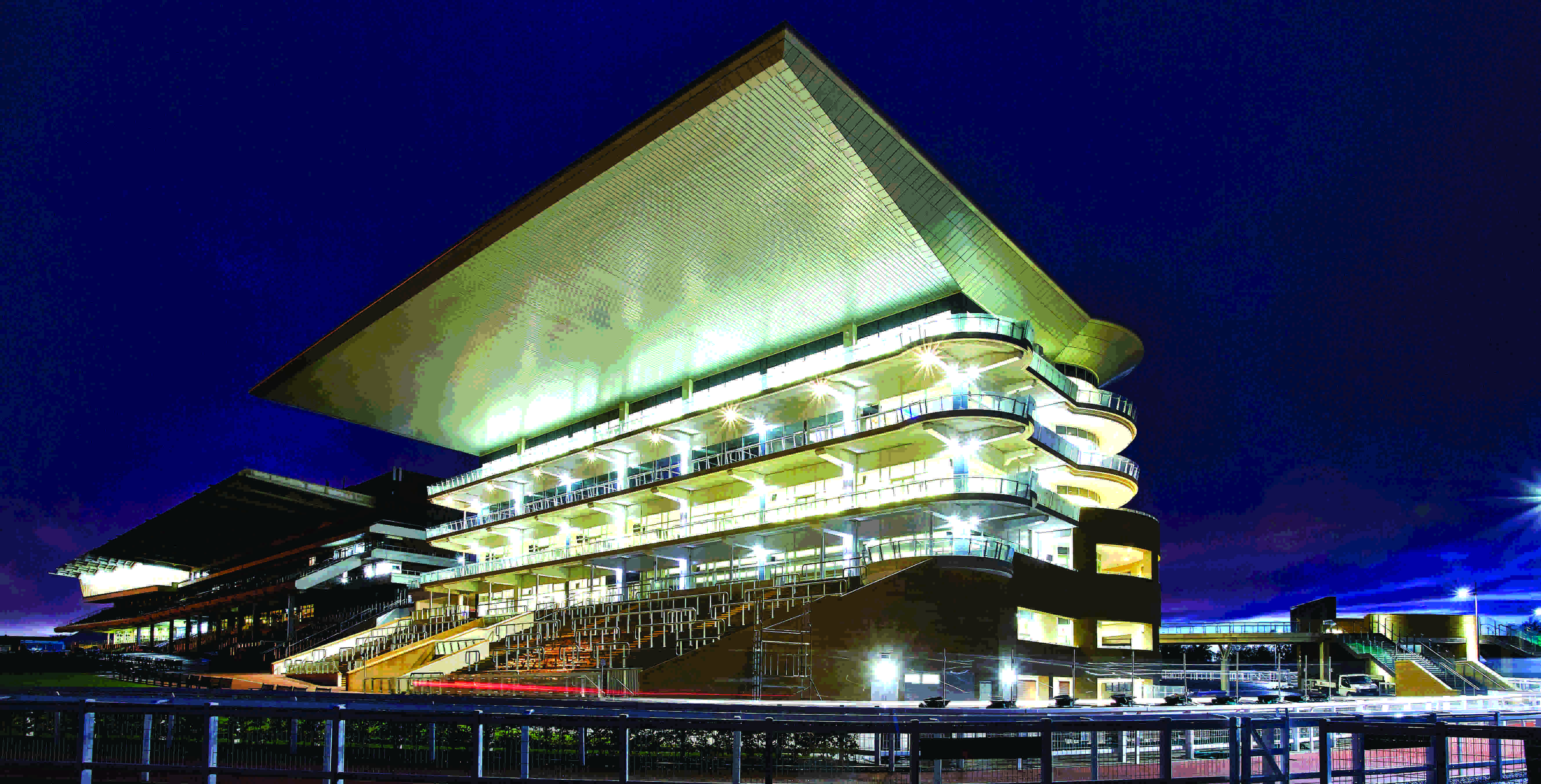
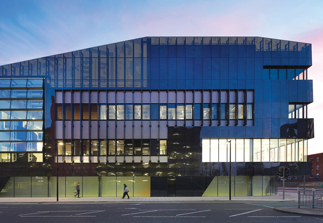
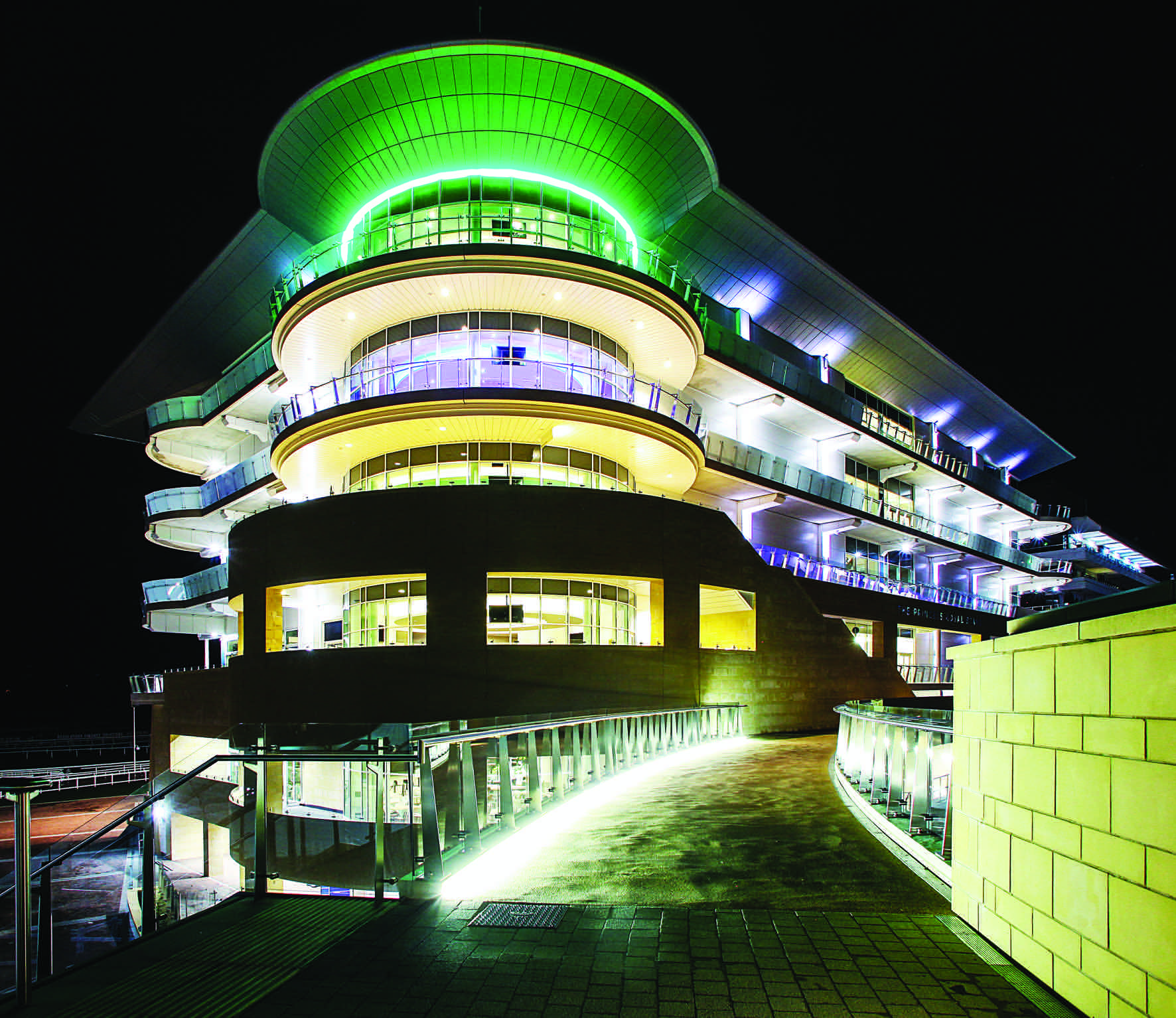
The grandstand‘s appearance is even more striking at night
There is no provision for cooling the grandstand, except for the restaurant and royal box, because these are more likely to be occupied outside of the racing calendar. However, because of high occupancy levels and low sun path in winter, the grandstand is susceptible to overheating.
Using dynamic simulation, the overheating for each floor was evaluated, accounting for the ‘free cooling’ available because of the low external temperatures during the racing season. This showed that level one of the grandstand was the only floor to overheat. To mitigate the issue, openable windows were installed around the front façade of level one. Brise soleil was not an option, as this would block the view of the racing; in addition, the majority of the heat was generated by occupants, not solar gains.
High and low-voltage power distribution
Senior engineer, Matthew Anderson, says early surveys proved the existing 11kV infrastructure could be safely used as part of the new ring circuit proposal. This was unexpected, as past alterations had led to varying cable sizes and minimal record information. Historic utility bills noted a maximum demand load of 2MVA on the busiest race days; this value – in conjunction with a detailed load assessment – indicated a peak capacity of 3.5MVA, including the new development.
Several energy sources were reviewed, including providing the additional power by generator; however, a 25-year financial assessment found a £0.5m upgrade of the local network was in the client’s financial interest.
A new HV network was designed as an open-ring system, to give as much supply security to buildings as possible, using sections of the existing radial arrangement where practicable. The new grandstand and adjacent weighing-room building need a fully backed-up supply to ensure racing can continue in the event of electricity grid failure. Site constraints prevented a standby generator from being installed next to the point of supply, so a complex HV changeover system was implemented. This used the new HV ring arrangement, operating three motorised HV devices to isolate a section of the ring and change from mains supply to generator.
The rented generator, all earthing equipment and provisions for either an HV or LV generator – including a 1.5MVA step-up transformer – were provided 250 metres from the new buildings. The changeover timing and operation is managed by an automated supervisory control and data acquisition (Scada) system, ensuring digital interlocking between devices.
The works included installation of three new substations and the upgrade in capacity of a further two – each with individual requirements. Studies were undertaken to ensure safety systems and protective devices would operate as expected if a fault occurred. This included in-house network fault analysis and grading study reports for new systems, and a review of existing downstream LV devices where supply upgrades were provided.
BIM
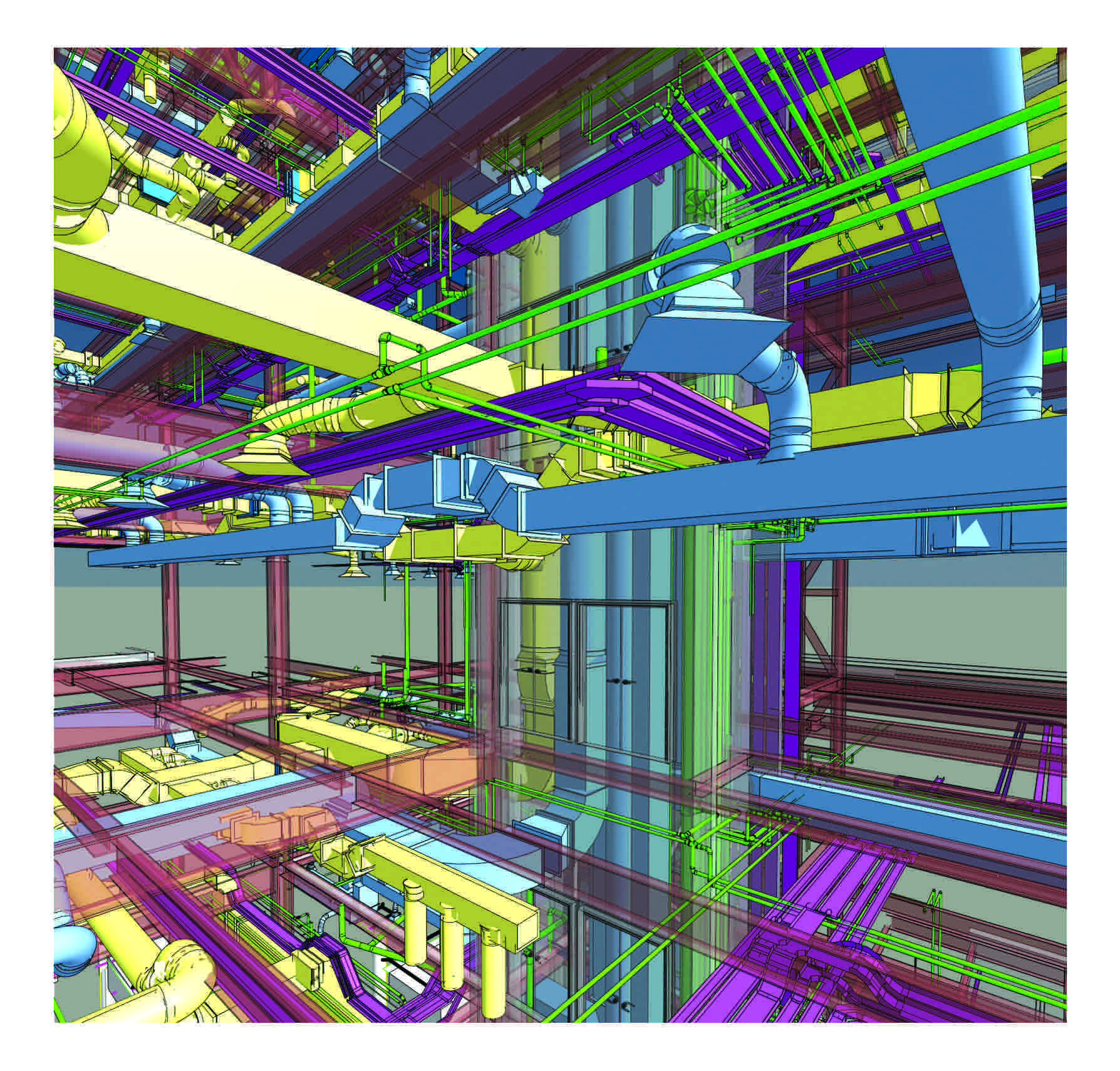
BIM software was used to provide coordination and clash detection in service risers
As only the structural engineers were working in Revit, the structural model became our base and was used – alongside the architectural 2D layouts – to design and coordinate the mechanical and electrical services.
We generated detailed plan drawings, instant sections, 3D views and video walkthroughs from the model.
A particular benefit of the 3D model was the ability to export it to a tablet computer, which was then used to show the coordination and access requirements in congested areas at design-team meetings.
The new grandstand has a dedicated substation housing two 1MVA transformers and motorised switchgear. Two transformers were specified to allow maintenance of one unit without compromising the electrical supply. The transformers operate independently during normal operation – one feeding the north rising busbar, and the other feeding the south busbar.
The building arrangement allowed for full electrical power separation, so half-floors could be individually isolated. A client request was for non-essential equipment to be remotely isolated through the building management system (BMS), to conserve energy and reduce the carbon footprint. This was achieved through the use of a contactor switching a non-essential distribution board within each riser.
Infrastructure
The site infrastructure design was extensive and included a complete replacement of the cableways and extensive work on the storm and foul-water systems.
The network of existing below-ground services was vast. Baileygomm identified that piles planned for the construction work would destroy the majority of existing cable ducts and drainage routes, so enabling work was required to divert these services and ensure safety during the project. This additional phase was designed – and works completed – within the initial stage E timeframe, to avoid impacting the construction programme.
Services such as television and radio media, betting and racing integrity were diverted with sufficient time to ensure all racing events could go ahead. Some services were required to meet minimum requirements of the British Horseracing Authority’s rules of racing.
Lighting
Principal engineer, Neil Cope, says the lighting design had to have a ‘wow’ factor and be highly efficient. The specification of LED luminaires ensured efficiency targets were met and allowed for more creativity than with other lamps. We were able to run flexible LED lighting tape in more unusual locations and smaller spaces than we could have done with cold cathode or fluorescent lamps.
Unbroken lines of light rise up the columns in the main, ground-floor area of the grandstand. Bespoke luminaires were designed and located under the radial deck, providing ambient lighting in their standard setting. These incorporate a secondary luminaire to increase lighting output on dull days.
There is a higher specification of lighting as you move up the grandstand, to reflect the increasing exclusivity of the spaces. The ground floor has a combination of downlights and cove lighting, while the first floor has a champagne bar with large diameter luminaires, designed to mimic champagne bubbles.
To benefit from the efficiency of LED lighting, absence control is a large part of the lighting-control strategy. For the front-of-house areas, DALI was chosen because of its flexibility, allowing luminaires to be controlled individually, so aiding scene setting.
The external lighting on columns needed to be combined with multiple services, including CCTV cameras, PA speakers and Wi-Fi units. Some of the columns are 10 metres high, so detailed wind calculations had to be performed to guarantee structural integrity.
The external lighting consists of power supplies from multiple buildings. To ensure luminaires switch on simultaneously, all circuits are controlled via a single photocell and time clock within the site BMS.