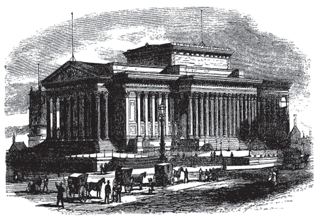
Described by Queen Victoria as a building ‘worthy of ancient Athens’, the neo-classical St George’s Hall, Liverpool, is the epitome of Grecian grandeur.
But the façade isn’t its only claim to fame. The building, which hosted Charles Dickens’ world premiere reading of A Christmas Carol in 1866, is also home to the world’s first modern air conditioning system, designed by Dr David Boswell Reid.
First operated in December 1851, Reid’s ‘systematic ventilation’ led the design of the building, which he claimed was the only one where he had been given a sufficiently free hand to install the system he envisaged.
Although the term ‘air conditioning’ was first used about 75 years later, this article will show that his system at the Liverpool concert hall had all the necessary elements to describe it that way.
The layout
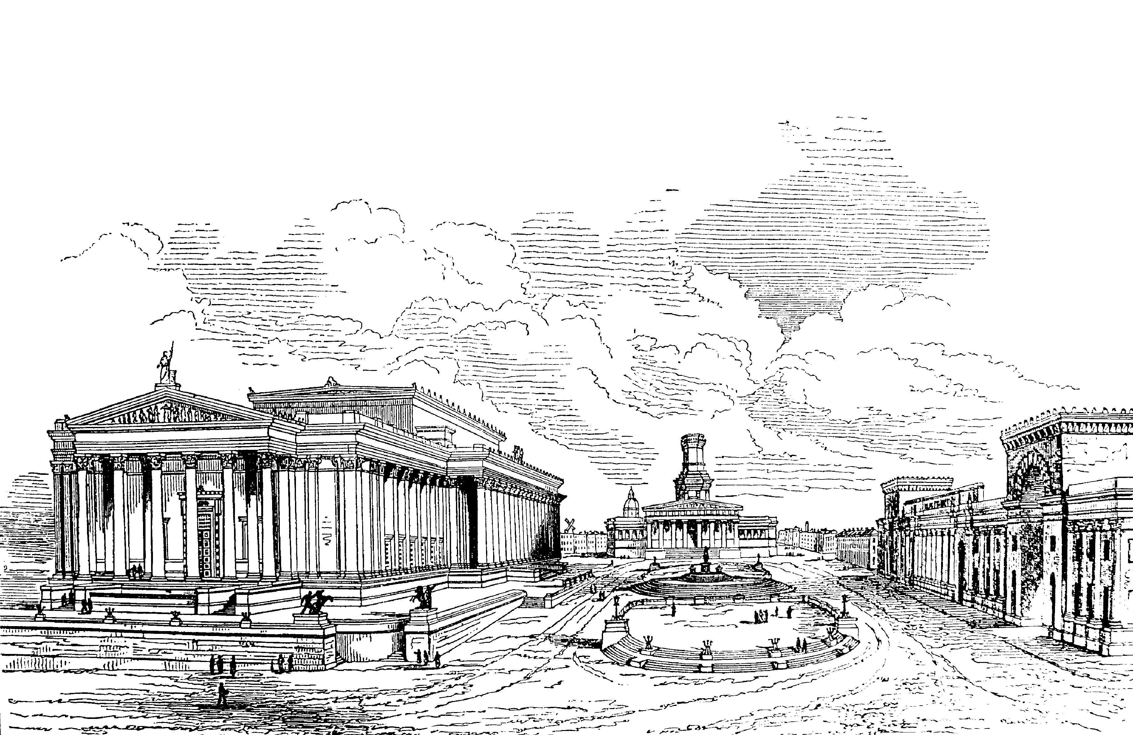
The building has an unusual – and probably unique – combination of justice and entertainment combined in a single edifice, where five major spaces are spliced together, rather than joined end-to-end.
This combination of functions came about when two separate architectural competitions in 1839 – to design major public buildings in Liverpool – had been won by the same architect, Harvey Lonsdale Elmes of London.
Although Elmes was only 25 years old and relatively inexperienced, he had designed a number of buildings in Prince’s Gate and Birdcage Walk in London, and had already won a competition in Liverpool to design a new school for Liverpool College (which later became the Liverpool Collegiate School).
The competitions were for a concert hall (to be funded by public subscription) and the Assize Court Building, to be paid for by a Treasury loan under the Liverpool Improvement Act.
When Elmes was asked how the two might be arranged to create a public forum, he offered to combine the buildings and produce a structure that was bigger than any other throughout the land. This immediately sold the idea to the council.
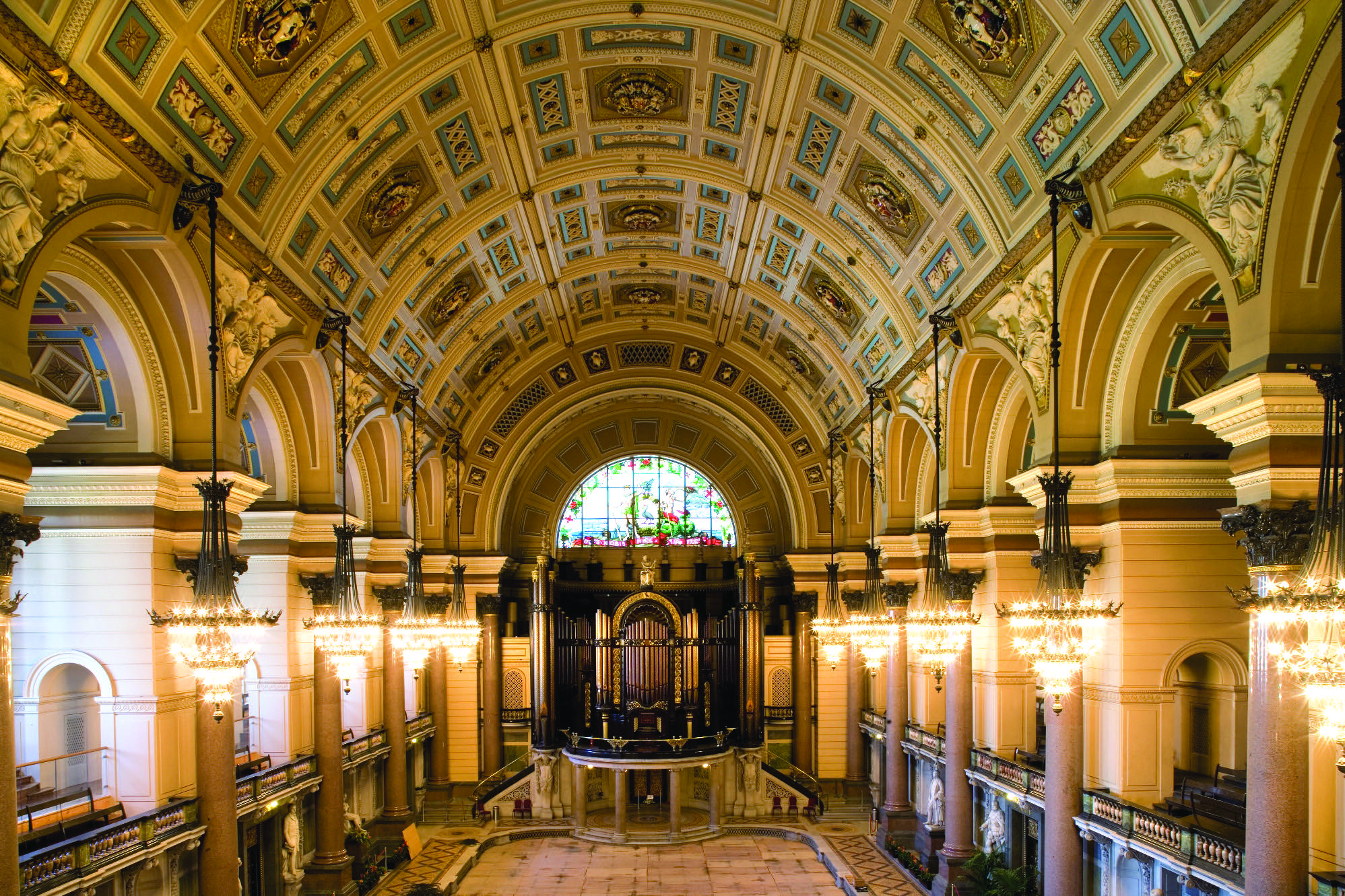
The Great Hall
The influence of Reid
Soon after Elmes’ official appointment, he requested that the council consider employing Reid as ‘ventilator’.
Elmes was aware of Reid’s work at the Palace of Westminster and had almost certainly attended one or more of the lectures Reid gave on ventilation, primarily in London’s Exeter Hall.
Reid was formally appointed in July 1841 to fulfil the same role in St George’s Hall, making it clear that he would be unable to spend a great deal of time in Liverpool.
The degree of control afforded to Reid is evident in a letter – dated 9 August 1841 – from Elmes to the structural engineer, Robert Rawlinson, less than a month after Reid was appointed.
When referring to the ‘positions of the benches both longitudinally and transversely’, Elmes instructs Rawlinson to take into account ‘the area of 400ft superficial (section) for the vitiated air to pass’. He goes on to say: ‘You will oblige me, therefore, by referring to the ventilation plans which are correct.’ In a further letter to Rawlinson, dated 27 September 1841, Elmes refers to his ‘definitive’ plan, saying that: ‘Dr Reid wished some alteration made in the course of the smoke flue, which incurs the necessity of placing the bench considerably higher up the ground.’
It is apparent that both architect and structural engineer were being dictated to by the requirements of the ‘ventilator’ before work had even started on site.
Reid’s system
An air-conditioned building requires control of: temperature (up or down); relative humidity (up or down); air throughput rate; and air filtering or cleaning. Reid’s system combined all these elements, although the amount of cooling available depended on the temperature of the town’s water in the mains system, as there was no means of refrigeration.
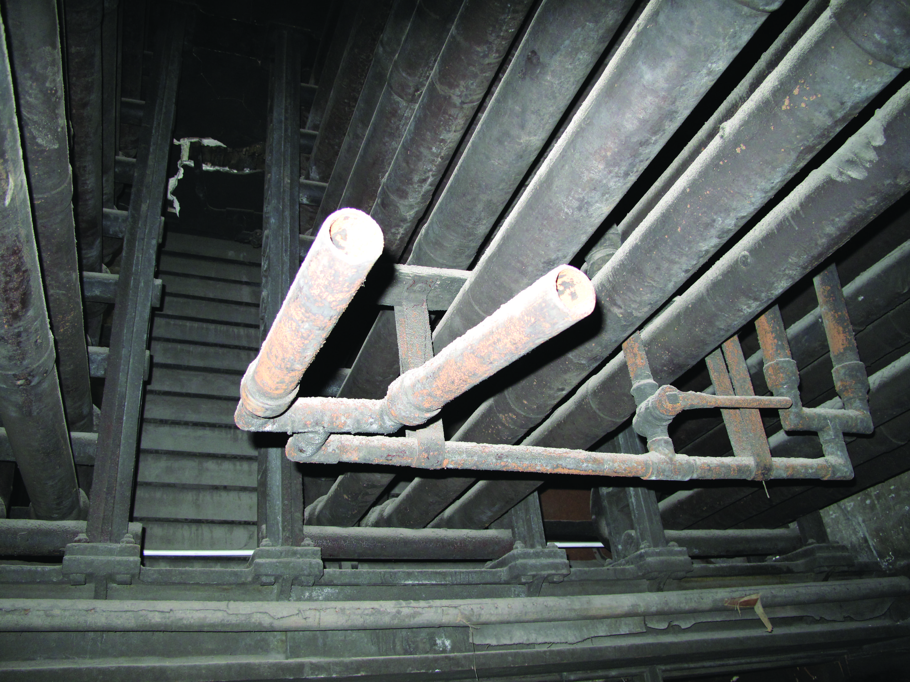
Figure 1: Steam injectors below main heating coil
The temperature of the supply air was controlled by passing it over one or more of the five large heater batteries comprising 4-inch (100mm) cast iron pipes containing hot water in winter and cold water (from the town mains system) in summer.
Another 27 coils were fed from steam boilers, but Reid anticipated that these would only be used in extremely cold weather or for pre-occupancy warm-up. The elaborate arrangement of connecting ducts allowed the final supply temperature to each of the major spaces to be varied by mixing warm air with cold, fresh air.
The two main fresh air supply shafts each contained a cold-water fountain providing a fine mist. These reduced the moisture content in summer and provided a degree of adiabatic cooling, but their main purpose was to clean the air. It then passed through a vast thermal labyrinth of brick columns and arches, where impurities would be deposited.
Reid was aware that moisture needed to be added to the warmed air in winter for the occupants’ wellbeing. This was achieved through nozzles that injected steam directly into the airstream. This came from a small boiler, which had been included in his design for this sole purpose (Figure 1).
The air was extracted by feeding the vitiated air into four exhaust shafts (see panel, ‘Proposed extract tower’), although air from the main hall roof space could pass directly outside. The original main hall roof had upstands with glass louvres for this purpose.
Proposed extract tower
By the time Elmes was being asked to consider the arrangement of the two competition buildings, the council decided to construct another building housing daily courts, including magistrates’ courts and a bridewell (central lock-up); this was also indicated on his plans.
Reid saw this as an opportunity to incorporate a communal extract tower for all three buildings, similar to the stand-alone tower he designed for the Temporary House of Commons.
The extract tower was to be 30ft (9m) in diameter at the bottom, and about 200ft (65m) high with a furnace burning permanently at its base. It was to be connected to the larger building(s) by underground tunnels so all vitiated air and chimney smoke would pass through it.
Elmes’ drawing, which appears in Reid’s 1844 book3, shows how it might appear. All of the 110 fireplace chimneys in the main building were to have flues that turned downwards. However, in April 1845, it was decided that the smaller building would not be built at that time (the Liverpool main bridewell and magistrates’ courts were eventually built around 1859 on a site nearer to the town hall).
The north end of the ‘forum’ was to be closed off by the daily courts and bridewell. The building on the right was the now-demolished classical front to Lime Street Station, which had been designed by borough architect John Foster Junior, in 1835.
In 1845 the Council decided that there were insufficient funds for the daily courts building but, by then, St George’s Hall was up to principal floor level and all the lower elements of the Reid extract system had been completed, so the way vitiated air and chimney effluent were to be extracted had to be completely reconsidered.
The tunnel connecting the lowest level of St George’s Hall to the proposed exhaust tower was then bricked up and forgotten about. (After working closely with the hall manager, this underground system is scheduled to be reopened for inspection
later this year). Four new exhaust ducts were then incorporated into the building and these terminate at the four corners of the highest roof behind the parapet.
The four exhaust shafts had braziers of coal constantly burning at the bottom; these were replaced by gas jets after a few years to reduce labour.
Special attention was given to the roof space of the Crown Court: being at the south end of the building, in sunny weather the vitiated air could discharge directly outside, with the extract rate being boosted by solar gain to the attic.
The air supply rate could be increased using large paddle fans driven by a steam engine, but Reid’s instruction manual1 makes it clear that this should only be necessary in the summer when the stack effect would be insufficient, or in winter for preoccupancy warm-up.
There were four fans, each 10ft (3m) in diameter with eight 5ft (1.5m) by 2ft 6in (0.75m) blades. These could be made to operate individually or in any combination, and the ‘mechanical’ supply rate could be varied from approximately 1,000 to 50,000 cfm (0.5 to 25m3/s).
Elmes’ drawing, which appears in Reid’s 1844 book
Typical arrangement
The small concert room system is almost identical to that applied more than 160 years later in the 2014 Stirling Prize-winning Everyman Theatre.
Fresh air for the concert room is taken from slightly above street level (in the 19th century Lime Street would have been heavily contaminated with horse manure), cleaned and passed through the thermal labyrinth before reaching the central distribution chambers.
This air is then either passed through – or around – the Great North Water Apparatus (one of two major hot water coils) containing 72 30ft (10m)-long pipes, each 4-inch (100mm) in diameter.
The air then passes along the main supply duct and splits left and right (west and east) before rising up two vertical shafts, arriving under the seating.
Air was delivered into the concert room primarily through a continuous grille in the riser under each row of seats, and additional supply came from the front of the stage and the front of the seating. Extra fresh air – delivered from special fresh air towers behind the lower roof parapet – can be supplied directly into the concert room from either side of the stage.
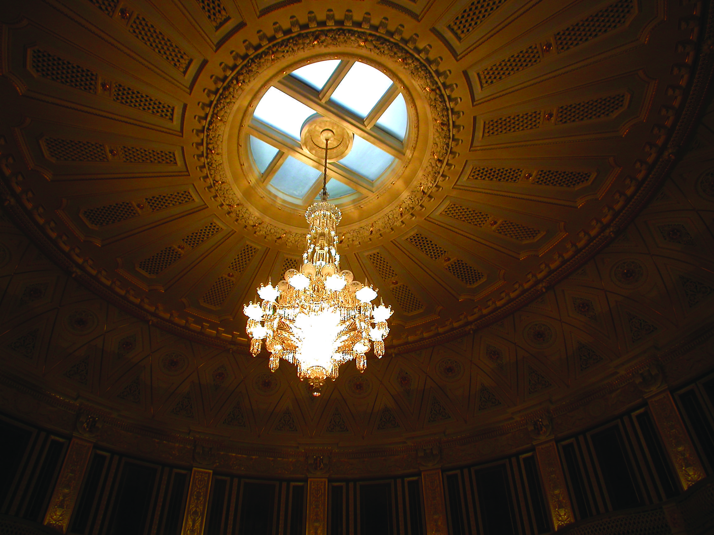
Figure 2: Concert Room ceiling showing roof-light and air outlets
The vitiated air passed into the roof space through numerous apertures in the ceiling, each with an adjustable flap behind it. In addition, and especially when the gas jets were lit on the chandelier, the glass quadrants in the roof light over the chandelier could be opened to allow excess heat to escape (see Figure 2).
Reid had persuaded the building committee that his system could be much smaller if the main hall was not used for functions while the courts were in session.
However, he made allowances to ensure that the concert room and the adjacent (north) court could be used simultaneously, and the direction the vitiated air from the concert room took depended on this.
Under normal circumstances the air from the concert room went to the north-east exhaust shaft but, if this court was also being used, the air from the concert room went to the north-west exhaust shaft. This ensured that sufficient drawing power could be applied to both at the same time.

The first air-conditioned building?
It could be argued that this was not Reid’s first attempt at air-conditioning a large space, and that the honour should go to the Temporary House of Commons in 1836.
However, St George’s Hall was the first building where such a system was integrated fully into its design and construction – both the architect and structural engineer relied on Reid to let them know his requirements before even the bench levels could be set.
Reid’s system was first used when the courts came into session on 8 December 1851, while the Houses of Parliament – using a similar system – were not used until February 1852.
A complete history of the design and construction of St George’s Hall can be found on the Heritage Group website. Read more on the pioneering work of David Boswell Reid in ‘The pioneer who rid Parliament of hot air’, January 2015 CIBSE Journal.
References:
1 Diagrams of the Ventilation of St George’s Hall and the New Assize Courts, D B Reid, 1855 (Liverpool Record Office).
2 HEVAC heritage http://bit.ly/1Mevuvy
3 Illustrations of the Theory and Practice of Ventilation, D B Reid, Longmans, London, 1844.