Jaguar Land Rover engine manufacturing centre
Designed in 2012, the first phase of Jaguar Land Rover’s (JLR) Engine Manufacturing Centre set the benchmark for low carbon and sustainability in a manufacturing environment.
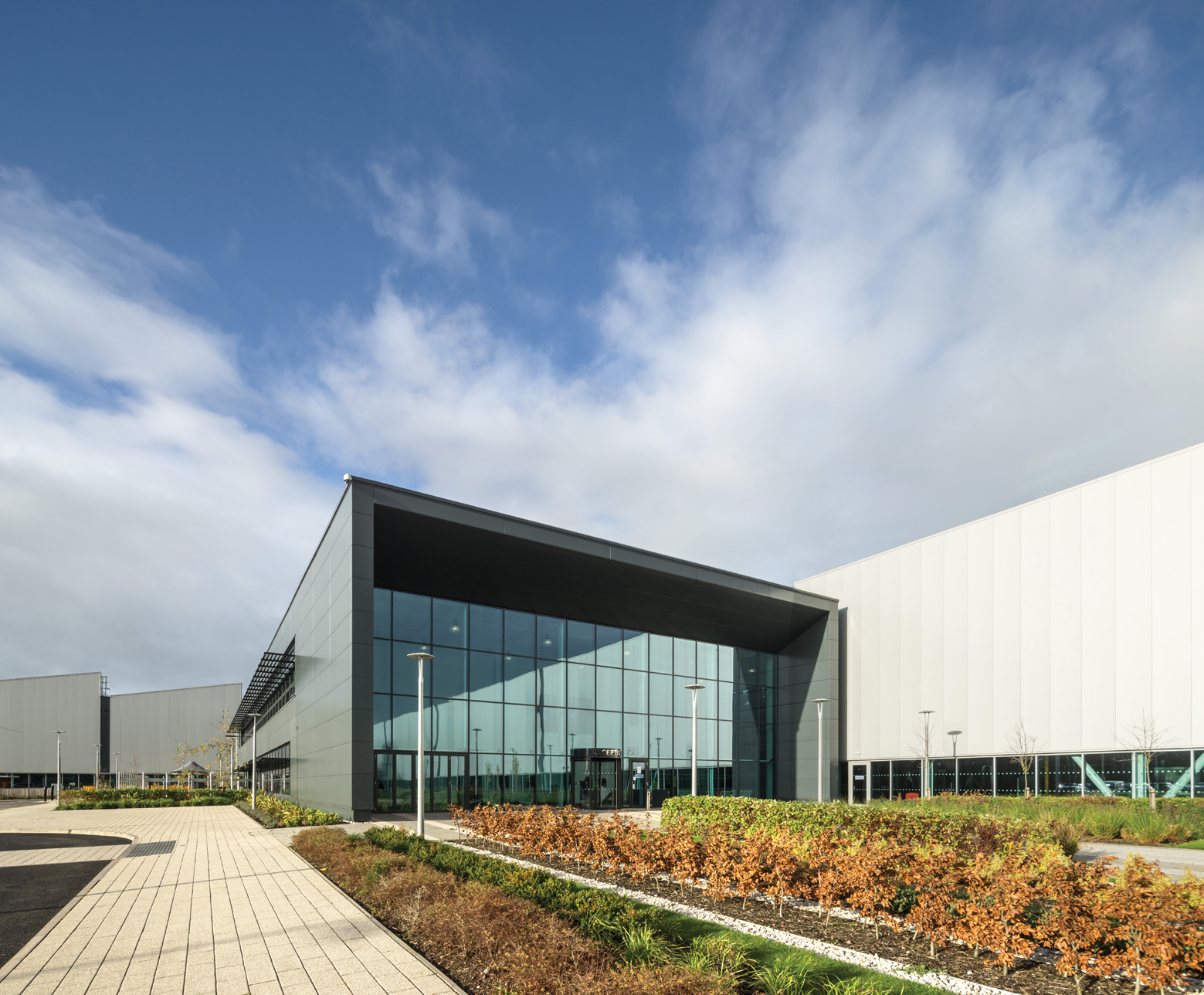
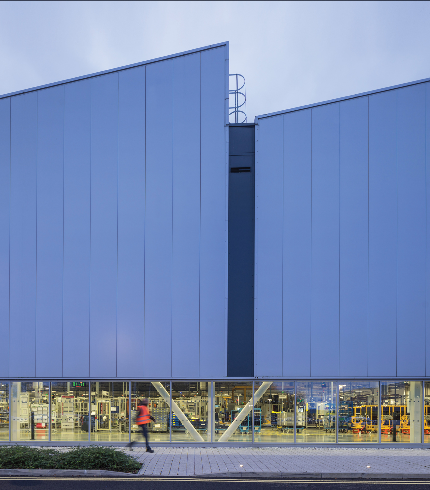
Located on the i54 Business Park near Wolverhampton, the carmaker’s brief to project architects Arup Associates was to create 100,000m2 of production space; deliver a showcase for sustainability through design, operational and process performance; and achieve a Breeam Excellent rating.
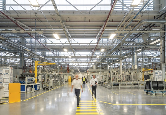
The first phase of the project is based on three linked, rectangular buildings, each measuring 180m x 135m. One of these houses the machining hall, where the engine block, head and crank are precision made. The other halls house the assembly operations, where component parts are put together to produce a finished engine. In plan, the machine hall and the first assembly hall are offset, and linked at one corner by a two-storey staff-support and administration building.
Project team
Building services engineer: Ove Arup & Partners
Building owner and occupier: Jaguar Land
Rover (JLR)
Project manager: Stace
Quantity surveyor: Davis Langdon
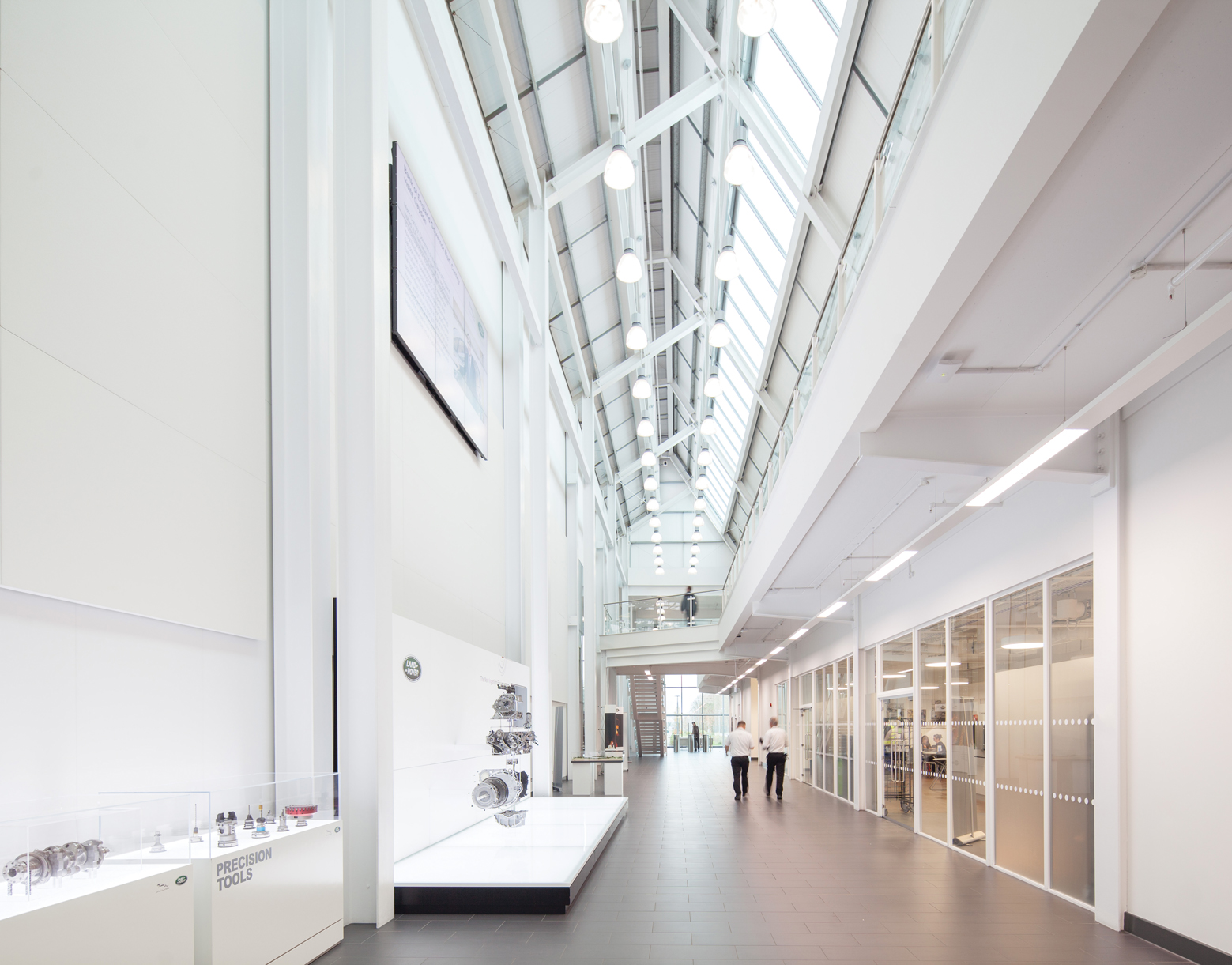
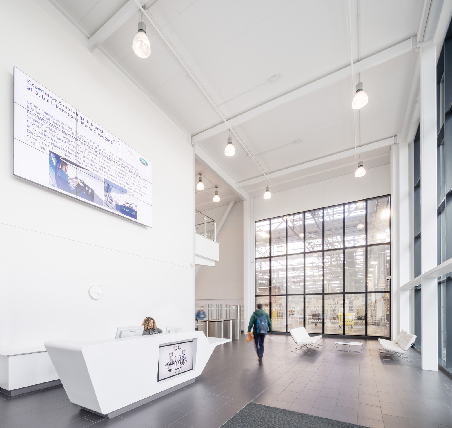
All the buildings feature glazed façades – an architectural solution intended to blur the boundary between production and support spaces, and to enhance communication between staff working in the different areas. The glazing also enhances the working environment by offering views onto the landscaped surroundings and, importantly, allows daylight to enter the huge halls.
For the three main buildings, the daylit perimeter is enhanced by north lights set into the building’s saw-tooth roof profile. ‘We were keen to introduce natural light throughout the halls, to provide an appealing daylit working space and, by daylight dimming the lighting, it helps save energy, too,’ says Philip Hives, an associate at Arup and the project’s building services engineer.
To meet JLR’s sustainability objectives, the glazing – along with the rest of the building fabric – exceeds the minimum elemental U-values in the Building Regulations. The high levels of energy used by manufacturing processes, and the subsequent heat gains, meant there was little benefit in improving the fabric energy performance further.
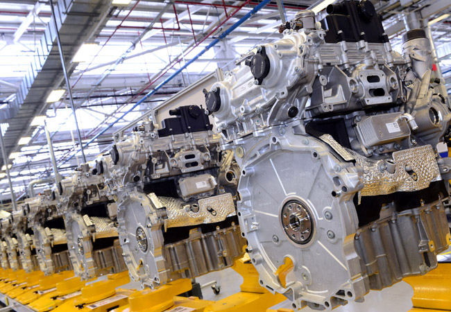
Engines on the production line
The buildings are supported on a steel frame; the structural grid for the machining hall is 30m x 15m, while the assembly halls have a 30m x 30m grid to maximise options for reconfiguring the assembly line.
The machining hall is heated, using an all-air system, via 84 terminals located 3m above the shop floor; six air heating units (AHUs) supply 85m3/s of air to the space. ‘Roughly half the volume of air supplied is needed to maintain the hall’s temperature at approximately 20oC. The other half of the volume is make-up air needed for the oil-mist extract system,’ explains Hives. Oil mist is created by the milling machines, so a local extract system is installed to prevent this vapour from entering the production space. In addition, a small quantity of fresh air – equivalent to about 0.25 of an air change per hour – is introduced to the hall for the occupants.
Hives says the huge volume of air in the machining hall means temperatures ‘tend to be relatively stable’. In winter, heat given off by the process equipment helps maintain a steady temperature; top-up heat is supplied by indirect, gas-fired heater batteries in the AHUs. Arup opted for gas heating because the building size means pipe runs are long, and heat losses and pump losses would have been significant if a water-based system was used.
There is no provision for make-up air because of concerns that unfiltered air would introduce particulates that could affect machining tolerances
If the hall gets too warm in summer, vents in the north-light windows can open to let out the hot air trapped beneath the roof. ‘This facility is there in case it’s needed to deal with future changes to the manufacturing process,’ says Hives. There is no provision for make-up air. This is partly because of concerns that unfiltered air entering the space would introduce particulates that could affect the machining tolerances – which might also have an impact on the clinically clean production process.
To ensure there is no airborne contamination, the supply of air to both halls is filtered to class F9.
The engine assembly halls are heated using air; however, they also have 2MW of cooling installed. Both heating and cooling are supplied using a displacement ventilation system. The halls’ huge volume is reflected in the 71m3/s of air supplied to each one by five AHUs via displacement terminals. The air is used to maintain a steady temperature and most air is recirculated, with only a small proportion of fresh air introduced for the occupants. To maximise flexibility in positioning and relocating process plant, the displacement terminals are located 3m above the shop floor. The assembly halls have a target temperature of 20oC at 3m above the floor, rising to 26oC at high level.
To maintain production flexibility, all services are generally routed through a zone 7m above the floor. ‘We had a 2m space for services distribution, which we shared with Jaguar Land Rover’s process services, before we reached the 2.5m structural zone beneath the roof,’ says Hives. These high-level services were supplied as prefabricated modules to minimise the amount of work carried out at height, increase the speed of installation, and ensure the quality of workmanship.
Renewable energy
As part of the scheme’s low-carbon design, the buildings feature a roof-mounted photovoltaic array. The design team built upon an earlier low- and zero carbon energy study by Arup, which established roof-mounted PV and solar thermal installation as a favoured option for carbon savings. More detailed option studies examined the viability of different sizes of PV arrays, including one covering the entire roof, which would save more than 2,000 tonnes of CO2 emissions per year and have a simple payback of 8.5 years. JLR funded this option, and the 21,000 panels – the largest rooftop array in the UK at the time of installation – can deliver a peak of 5.8MW of power.
A more unusual source of electrical energy is supplied by the dynamometers, which are used to test a sample of engines from the production line by imparting a resistance to check their performance.
Other renewable technologies incorporated into the project include solar thermal panels to heat domestic hot water for the central facilities building. Panel payback was estimated to be 10 years for the installation sized to match the building’s 70kW base load for domestic hot water.
The central facilities building also features a transpired solar collector wall to preheat the supply air to the staff changing facility. This consists of a skin of dark, perforated, profiled steel cladding, which is installed on the units’ south-facing wall in place of standard cladding. The outer steel skin is separated from the inner, insulated wall by an air cavity. As sunlight strikes the outer skin, solar energy is absorbed, warming the perforated steel skin and, subsequently, the boundary layers of air in contact with the inside and outside of the steel. A fan draws the warmed air out of the cavity and, as it does so, the air in the outer boundary layer is drawn into the cavity through the hundreds of perforations in the outer skin, to increase the amount of heat collected by the system by up to 50%.
The fresh air preheated using the solar wall is ducted to the intake of the changing room AHU. ‘The changing room’s heat load was compatible with the maximum area of façade available on the facilities building’s southern elevation – and because the area is operational 24 hours a day, it helps to maximise the opportunity for free heating,’ Hives says. Top-up heat is supplied by heater batteries from a small LTHW system serving the support area.
The transpired solar collector contributes to preheating 5 m3/s of supply air. If the technology had been used to preheat air supplied to the main halls, it would have needed to preheat approximately 71 m3/s.
Monitoring
An energy-management system is being used both to monitor consumption and target improvements by JLR, with input from Arup’s building performance and systems specialists. The sophisticated network enables separate metering of building systems all the way down to individual AHUs; it also meters the process energy used at each stage of production.
To optimise building performance, JLR commissioned Arup to monitor the building throughout the seasons. These findings were used to target energy improvements. Soft Landings is used on the project. Interserve and MEP contractor Interserve Engineering Services took the lead in managing the commissioning of their respective works, which began with the advance planning for their input during handover and for the subsequent two years. They demonstrated the systems to the client in readiness for handover, and remained involved beyond that to offer support during the liability period.
The controls installer, Schneider, took the lead role in managing interfaces between the building management system (BMS) and other systems, and was responsible for the metering and energy management system (EMS). This was successful in ensuring systems were functional at handover; they were then extensively commissioned during the process fit-out. This has allowed the refinement of controls and metering, so the BMS and EMS now function in accordance with JLR’s specific needs.
‘There was a very good energy management system put in along with the BMS to allow Jaguar Land Rover to monitor what is happening within the building and to highlight areas that can be improved,’ Hives says. ‘The building is performing well – better than we predicted it would – and Jaguar Land Rover is making continuous improvements to bring loads down even further.’
The judges for the 2017 CIBSE Building Performance Awards were impressed with the scheme, describing it as: ‘One of the most comprehensive entries received for an outstanding project, particularly in considering how the building could contribute to the reduction of emissions associated with “process” energy.’
■ See all 2017 CIBSE Award winners at www.cibse.org/bpa