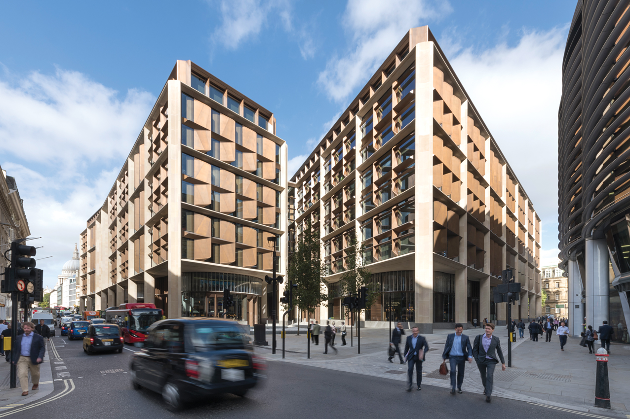
In the heart of the City of London, close to the Bank of England and St Paul’s Cathedral, is a giant, bronze-clad office building being hailed as an exemplar of sustainability. It is Bloomberg’s newly opened European headquarters, which reportedly cost £1bn and occupies an entire city block. The office actually comprises two buildings, linked by bridges that cross a Roman road that has been reinstated on the site as part of the scheme.
What sets this project apart from its neighbours is that the Bloomberg building has a Breeam Outstanding environmental rating, with a score of 98.5% – the highest design-stage score ever for a major office development. This unparalleled rating has been achieved by the design team of architect Foster + Partners and building services engineer Sweco, in response to a challenge by company founder Michael Bloomberg ‘to push the boundaries of sustainable office design’.
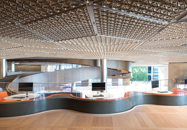
The chilled ceiling enables the natural-ventilation concept to work for extended periods
The scheme features vacuum drainage, a combined heat and power (CHP) system, an absorption chiller and a bespoke chilled ceiling, and it incorporates a hybrid natural-ventilation option. As a result, the nine-storey development is expected to use 73% less water and 35% less energy than a typical office.
One of the more innovative aspects of the design is that the larger, northern building’s expansive, deep-plan floor plates can be ventilated and cooled using natural ventilation. Outside air will enter the floor plates through the purpose-designed, vertical bronze fins that line the building’s façade and frame the glazing. The fins incorporate acoustically treated vents that open and close to control airflow. From the floor plates, the air will rise up and out of the central atrium.
It is only the northern building that incorporates natural ventilation; the smaller, southern building does not have an atrium and, as a consequence, is mechanically ventilated.

The ceiling petals create a large surface area in contact with the pipework behind, to raise the chilled water temperature
The building’s large floor plates meant it was particularly challenging to develop a natural ventilation solution for the office. Foster + Partners, with help from Wirth Engineering and Breathing Buildings, developed a system that enables this leviathan to naturally ventilate in mid-season, and is programmed for commissioning in time for milder weather next spring (see panel, ‘Helping the giant
to breathe’).
In summer and winter, when the façades are sealed, the office will be mechanically ventilated with air supplied from roof-top air handling units (AHUs). The air is ducted down five perimeter cores for distribution via diffusers in the back of the office’s integrated ceiling. Air is extracted from above the ceiling, close to the cores.
‘The systems are set up for 4,500 people in the building, but at any one time a reasonable proportion of these will be out, and others will be in meeting rooms et cetera – so if we had designed the system on a constant-volume basis, we’d have had to supply unnecessarily large quantities of outdoor air,’ explains Trevor Farnfield, operations director at Sweco, and design director for the project.
Instead, each floor – typically containing 700 to 800 workstations – incorporates 60-70 integrated CO2 zonal sensors linked to the building management system (BMS). ‘What we’ve done is run the system on a variable air volume basis, by moving air around the building to follow where the people are, which gives significant energy and carbon savings,’ Farnfield adds.
The office floor plates feature a bespoke, integrated ceiling, which was proposed by and developed with the architect. ‘The chilled ceiling enables the natural ventilation concept to work for extended periods,’ says Farnfield. The solution – developed over ‘an extensive period of time and many iterations’ – was led by Foster + Partners’ partner Irene Gallou and is a filigree of polished aluminium petals, ‘inspired by the pressed metal ceilings of New York’.
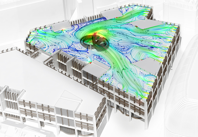
Air flow model
Chris Trott, Foster + Partners’ head of sustainability, used rapid prototyping to test many configurations of fin inlet and, subsequently, they developed a full-scale, off-site, pre-commissioning mock-up of the office, to refine and optimise the operating characteristics and comfort.
The development process allowed for a highly integrated solution, in which the petals create a large surface area in contact with the chilled water pipework behind. This feature raises the water’s temperature from the more usual 13°C to 16.5°C. This has two main benefits: it reduces the amount of cooling energy needed and it lowers the condensation risk when the building is operating in hybrid mode and cooling is used to trim the lateral heat gains picked up by outside air moving across the floor plates.
Chilled water is supplied from either basement, water-cooled chillers – there are four units producing 1,850kW each – or from roof-mounted, critical back-up, air-cooled chillers – four units producing 550kW each.
LED lamps are incorporated into the ceiling, with the petals acting as light reflectors. Lighting levels are 300 lux, with a power load of 4.7W/m2. ‘Because the lighting load is so low, it has the secondary benefit of reducing the cooling needed to offset heat from the lights,’ says Farnfield.
The integrated ceiling panel is pushed tight to the underside of the structural steelwork, to maximise the 2.9m floor-to-ceiling height on the large floor plates, so all services have to pass through the structural steelwork. ‘It was quite a challenge,’ says Farnfield. ‘We ended up with 25,000 holes in the steelwork.’
In winter, fan units – incorporated into the ceiling’s perimeter edge detail – offset heat losses using heat from the three, 520kWe basement CHP units. These are sized to meet a base electrical load of 1.5MW, are controlled on electrical demand, and run in parallel with
mains electricity.
There is a proper soft landing for this building, which will include seasonal commissioning, because you cannot pretend you know how the building will function on day one – Shaun Fitzgerald
‘Heat generated by the CHP units is used by an absorption chiller to cool three large comms rooms, hidden in the basement, as well as other technical facilities,’ says Conor O’Donoghue, operations director in the buildings team at Sweco.
The CHP units are one layer in a fully resilient N+N electrical system. The building has two incoming 33kV supplies, from different UK Power Networks primary substations, which are transformed down in the building so there is no single point of failure. All critical facilities have standby generation, while an uninterruptible power supply (UPS) ensures continuity of supply.
Perhaps the most unusual building services innovation is the vacuum drainage. This came about because – when Bloomberg issued the sustainability challenge – he made it clear that the organisation was looking to reduce its water consumption. ‘We put forward a proposal for a vacuum drainage system as part of an integrated water conservation strategy,’ says Farnfield. It was an inspired decision: there are more than 450 toilets in the building and a typical flush on a vacuum drainage toilet is 0.8l/s of water – 20% of what a traditional WC installation would use. ‘It gives us a massive water saving,’ says Farnfield.
In total, five vacuum systems have been installed, each serving one or two vertical blocks of toilets. ‘It gives you a resilient solution, in case there is a problem with one of the vacuum systems,’ adds Farnfield.
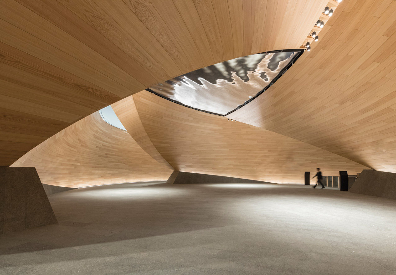
The curved timber of the Vortex makes for an impressive lobby area
With water consumption significantly reduced by the vacuum system, it is possible to flush the toilets using only harvested rainwater and water recycled from wash-hand basins and showers. The harvested and recycled water is passed through filters in the basement before being used for flushing.
‘Effectively, the building uses no mains water for flushing toilets,’ says Farnfield, who anticipates that 25 million litres of water a year will be saved as a result of this solution, equivalent to filling 10 Olympic-sized swimming pools a year. In addition, there are savings in drainage infrastructure costs linked to water consumption.
‘I believe a lot more of these systems will be used in the future, because they use a lot less water, which takes pressure off the mains and an equivalent pressure off drainage from the site,’ Farnfield says. A good idea going down the drain – or not, in this case.
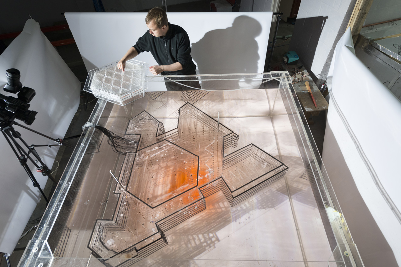
In collaboration with Foster + Partners’ model makers, Breathing Buildings constructed the world’s largest water-bath model, to show that getting the airflow to move across the floor plates was going to work
Helping the giant to breathe
Foster + Partners worked with Wirth Engineering and Breathing Buildings to develop a natural ventilation solution for the Bloomberg building. Breathing Buildings CEO Shaun Fitzgerald explains
The challenge of any natural ventilation system is that people need to be near an external wall, a roof or an atrium to benefit from fresh air. This building is multi-storey and deep plan, so you cannot say it will be naturally ventilated under all conditions, use profiles, types of space and weather conditions. One of the big challenges for a deep-plan building is how to get natural ventilation to work for large floor plates. With the Bloomberg building, we will bring fresh air in through the perimeter and across the floor plates to the atrium, where it will rise up to exit from the roof.
Chris Trott, of Foster + Partners, developed the approach in house – including the CFD modelling for the rapid prototyping. When the fin characteristics were known, Wirth Engineering was commissioned to carry out what is believed to be the largest CFD study ever undertaken.
This looked at the air movement from outside to inside the building, and the CFD used full coupling of the outside and inside airflows. In collaboration with Foster + Partners’ model makers, we constructed the world’s largest water-bath model, to show that getting the airflow to move across the floor plates was going to work.
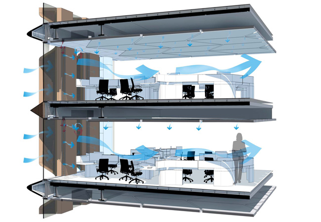
Air flow diagram
The model was also used to confirm the CFD and analysis, which showed that natural ventilation might not be effective for some floors if they were all linked. The biggest risk was that the upper floors would become part of the exhaust air pathway for the lower floors. We managed this by divorcing the top floor from the atrium, as far as the air is concerned, because it has roof access. The floor below has its own challenges and has had special treatment; the lower floors work fine.
The openings on floor seven need to be open wider than on floor two, because the buoyancy-stack effect you have available on the higher floor is less than on floor two. We did a lot of work with Foster + Partners to develop the control algorithm for the vent openings, to balance airflows within a given floor and to manage temperature differences between the floors. Effectively, you have to sacrifice some of the ventilation rate you could have achieved on floor two for the benefit of people on floor seven.
Another big problem when you have a 30-metre floor plate is the heat gain the air will experience as it moves across the floor. Natural ventilation might remove much of the heat from the space, but – nearer the atrium – you will need to ensure that cooling is available from the chilled ceiling to limit the heat gain.
Natural ventilation for this building is most definitely a hybrid. We exploit the benefits of natural ventilation when possible, but have the option of sealing the building and running it under a fully mechanical solution. The system has been tested extensively by Fosters using mock-ups. There is also a proper soft landing for this building, which will include seasonal commissioning – because you cannot pretend you know how the building will function on day one. It will take at least a year to hone and refine the control algorithms.
Bringing Mithras Roman temple to life
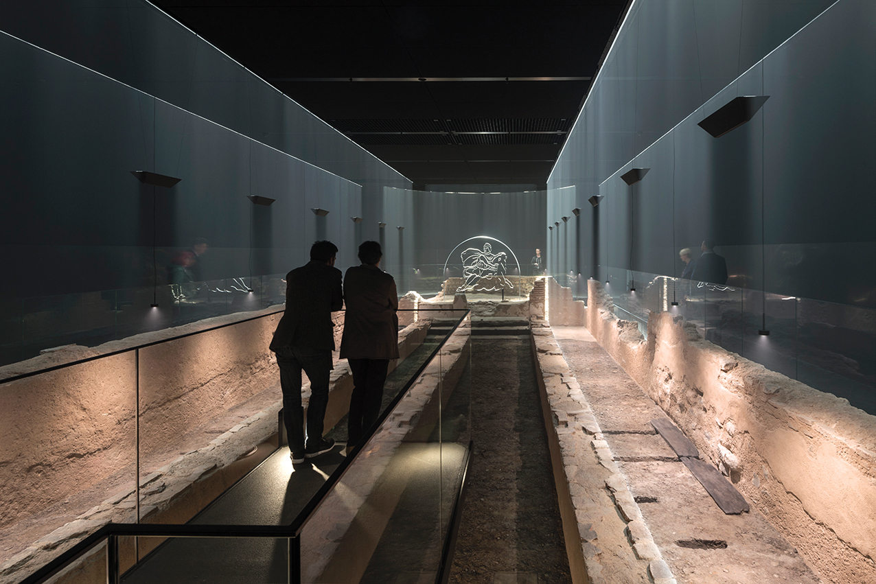
London Mithraeum uses light sculpture, haze and sound to bring the temple’s remains to life
Roman archaeology is embedded in Bloomberg’s new HQ. The building is bisected by a resurrected Roman road, while its basement contains the Roman temple of Mithras, built in the third century AD.
The temple was first discovered in 1954 – during excavations for the Bucklersbury office building, which previously occupied the Bloomberg site – and the remains were recorded, dismantled and removed. As part of Bloomberg’s redevelopment of the site, it was agreed that the 1,800-year-old temple would be returned to its original subterranean location.
The reconstructed temple now sits beneath the Bloomberg building – seven metres below modern street level – and forms part of a new cultural destination. Designed by US-based Local Projects, in consultation with the Museum of London Archaeology, the visitor experience includes a glazed viewing gallery running around the sides of the temple, and a platform suspended above its central aisle.
Light projected from above, onto baffles, creates the illusion of the long-gone temple walls and columns rising up from the haze-filled space. Courtesy of Bloomberg, London Mithraeum is free to visit, though booking is advised. Visit www.londonmithraeum.com
Project Team
Client: Bloomberg
Architect: Foster + Partners
Ventilation consultant: Breathing Buildings
Building services engineer: Sweco