For an alternative way to access this module, CIBSE member, Jos Brownlie provides a video reading the module: Module 263 recording
Decarbonising heat in commercial buildings has become one of the central challenges for the built environment. Heating and domestic hot water (DHW) remain major contributors to operational carbon emissions, particularly across large public-sector estates, hospitality, healthcare and education facilities that rely on fossil-fuel boilers.
The UK’s legally binding commitment to achieve net zero greenhouse gas emissions by 2050 is accelerating the transition away from gas-based heating systems. Electrification of heat is widely recognised as a primary pathway to achieving this transition, particularly as the UK electricity Grid continues to decarbonise through increasing renewable generation.
Heat pumps play a central role in this shift. However, conventional heat pumps using hydrofluorocarbon (HFC) refrigerants can face limitations in commercial retrofit applications. Many existing buildings operate heating systems designed around high water temperatures, often exceeding 60°C. These temperatures are typically required for legacy radiator systems or for large DHW demands in buildings such as hotels, hospitals and leisure centres. Conventional heat pumps may struggle to achieve these temperatures efficiently without system redesign.
At the same time, regulatory pressure is reshaping refrigerant selection. European and UK F-gas regulations are progressively phasing down high-global warming potential (GWP) refrigerants, reducing the availability of many synthetic HFCs. This has increased industry interest in natural refrigerants that offer both lower environmental impact and long-term regulatory certainty.
Carbon dioxide (CO₂), also known as refrigerant R744, has emerged as a promising option. CO₂ has a GWP of 1 and zero ozone depletion potential, and is classified as an A1 refrigerant, meaning it is non-flammable and of low toxicity.
CO₂ heat pumps typically operate using a transcritical cycle, which differs fundamentally from conventional vapour-compression systems. This cycle allows the production of high-temperature water, often more effectively than conventional systems in uses with large temperature lifts, making the technology particularly attractive for commercial heating and DHW applications.
Thermophysical properties of CO₂
The behaviour of a refrigerant within a vapour compression system is governed by its thermophysical properties. CO₂ differs significantly from conventional synthetic refrigerants, and these differences strongly influence system design and operation.
Figure 1 is a phase diagram for CO₂ at temperatures from -80°C to 80°C. The diagram is divided into regions representing solid, liquid, gas and supercritical states, separated by phase boundaries where transitions occur. Overall, the diagram illustrates that the state of CO₂ depends on both temperature and pressure, and highlights the absence of a liquid phase at low pressures, and the emergence of supercritical behaviour at higher temperatures and pressures.
One of the most important characteristics of CO₂ is its low critical temperature of approximately 31°C, combined with a critical pressure of about 73.8bar. In many heat pump applications, the temperature at which heat must be rejected exceeds this critical temperature. When this occurs, the refrigerant cannot condense regardless of pressure. Instead of operating as a conventional subcritical cycle with condensation, the system operates in a transcritical cycle.
The critical point is the highest temperature and pressure at which a pure material can exist in vapour/liquid equilibrium. In transcritical operation, the high-pressure heat-rejection process occurs above the critical point. Rather than condensing, the refrigerant passes through a gas cooler, where it remains in a supercritical state and cools sensibly.
During this process, the refrigerant temperature decreases continuously rather than remaining constant, as it would during condensation. This produces a temperature glide along the heat exchanger. The glide allows the refrigerant temperature profile to more closely match the temperature rise of the water being heated, reducing temperature differences and improving heat-transfer effectiveness.
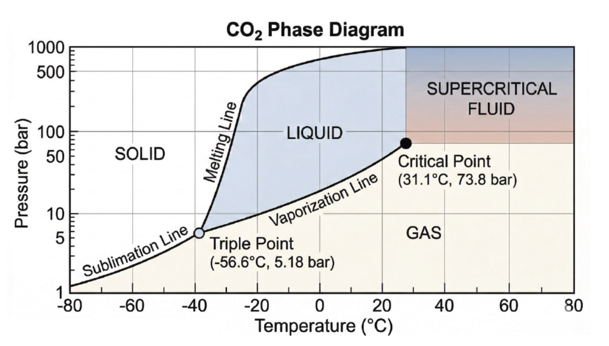
Figure 1: Phase diagram for CO₂ at temperatures from -80°C to 80°C. The triple point (−56.6°C, 5.18bar) marks the condition at which solid, liquid and gas can coexist. The critical point (31.1°C, 73.8bar) defines the upper limit of the liquid–gas boundary. Above this temperature, CO₂ cannot become a liquid regardless of pressure. Instead, it exists either as a gas at lower pressures or as a supercritical fluid at higher pressures, where there is no distinct separation between liquid and vapour
Several additional thermophysical characteristics reinforce these advantages. CO₂ has a high vapour density and volumetric heating capacity. This enables the same heating capacity to be achieved with smaller compressors and significantly reduced pipe diameters, which can be advantageous in plantrooms where space is constrained. The refrigerant also exhibits low viscosity and high thermal conductivity, resulting in high heat-transfer coefficients and allowing heat exchangers to be relatively compact.
Another important characteristic is the triple point of CO₂, occurring at approximately -56.6°C and 5.2bar.1 If pressure falls below this level, CO₂ can solidify into dry ice. System safety design must therefore ensure that pressure relief and venting arrangements prevent conditions that could allow solid CO₂ to form and block discharge paths, particularly during rapid depressurisation or maintenance conditions.
While these properties create engineering challenges, they also enable a distinctive heat-rejection process that is well suited to high-temperature heating applications.
Thermodynamic operation of the transcritical CO₂ cycle
The key feature that distinguishes CO₂ heat pumps from conventional systems is the transcritical vapour compression cycle. While the basic components remain similar to other heat pump technologies – compressor, heat rejection heat exchanger, expansion valve and evaporator – the behaviour of the refrigerant differs because the high-pressure side of the system operates above the critical point.
The thermodynamic cycle is typically illustrated on a pressure-enthalpy (p-h) diagram – see Figure 2. In a transcritical CO₂ system, the high-pressure section of the cycle lies entirely above the saturation dome, reflecting the fact that the refrigerant does not condense during heat rejection.
Although the overall cycle resembles a conventional vapour compression system, several important differences influence how CO₂ heat pumps operate and how their performance should be assessed.
Compression (1 ⇒ 2)
The cycle begins with low-pressure vapour leaving the evaporator and entering the compressor at point 1.
The compressor raises both the pressure and temperature of the refrigerant. In typical commercial systems, the pressure increases from around 20-45bar at the evaporator outlet to approximately 80-120bar at the compressor discharge.2
During compression, the refrigerant passes through the critical point and enters the supercritical region. Above this point the refrigerant no longer exists as a distinct liquid or vapour phase, but behaves as a dense fluid with properties of both.
One practical implication is the high discharge temperature produced by the compressor, often exceeding 100°C2 – this being system-dependent and can be lower with optimisation. This enables the heat pump to deliver high-temperature water suitable for space heating or DHW applications.
Gas cooling (2 ⇒ 3)
After compression, the high-pressure refrigerant enters the gas cooler, where heat is rejected to the building heating system.
In conventional refrigerant heat pumps, heat rejection occurs through condensation at a constant temperature. However, because the CO₂ is above its critical temperature, it cannot condense. Instead, it cools while remaining in a single supercritical phase.
As the refrigerant flows through the gas cooler its temperature decreases continuously. This produces a temperature glide along the heat exchanger, rather than the constant temperature profile associated with condensation.
For building services engineers, this behaviour is important because it allows the refrigerant temperature to follow the temperature rise of the water being heated. The result is often a closer temperature match between the two fluids, which reduces temperature differences within the heat exchanger and improves heat transfer effectiveness.
This characteristic is one reason why CO₂ heat pumps can effectively produce high outlet water temperatures, particularly when heating cold water streams such as DHW supplies.
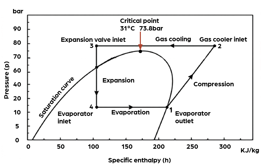
Figure 2: Illustration of the transcritical cycle of a CO₂ heat pump on a pressure-enthalpy (p-h) graph
Expansion (3 ⇒ 4)
After leaving the gas cooler, the refrigerant passes through an expansion valve.
The valve reduces the pressure of the refrigerant from the high gas-cooler pressure to the much lower evaporating pressure. This throttling process occurs without any useful work being recovered, making it inherently irreversible.
As pressure falls rapidly, the refrigerant temperature also drops and part of the fluid flashes into vapour. The mixture leaving the valve therefore consists of both liquid and vapour.
In CO₂ systems, the pressure difference across the valve is particularly large, so a relatively high proportion of flash gas is produced. Flash gas refers to vapour that forms immediately during expansion rather than within the evaporator, which reduces the useful evaporator heat uptake/cycle efficiency of the system. For this reason, the expansion process represents one of the largest sources of thermodynamic loss within the transcritical cycle.
Evaporation (4 ⇒ 1)
The low-pressure refrigerant mixture then enters the evaporator, where it absorbs heat from the source medium.
Depending on the system configuration, this source may be ambient air, water, ground loops or waste heat streams. As heat is absorbed, the remaining liquid refrigerant evaporates.
Unlike the gas cooler process, the evaporator operates below the critical pressure, so the refrigerant behaves like a conventional boiling refrigerant. The mixture gradually becomes saturated vapour and is typically slightly superheated before returning to the compressor at point 1.
Architecture and key components
The transcritical cycle leads to a system architecture that differs from conventional HFC heat pumps. While the main components are similar, they must be designed for higher pressures and specific control requirements.
The compressor draws low-pressure vapour from the evaporator and compresses it to the high pressures required for transcritical operation. Reciprocating compressors are commonly used in commercial CO₂ systems because they can reliably handle large pressure differentials and dense refrigerant. High-pressure scroll compressors are increasingly used in smaller systems. Variable-speed drives are frequently incorporated to match heating output to building demand and improve part-load efficiency.
In place of a condenser, transcritical systems use a gas cooler to reject heat to the heating circuit. Gas coolers may be air-cooled finned heat exchangers or water-cooled plate heat exchangers. In many commercial systems the gas cooler is optimised for domestic hot-water production, allowing cold mains water to be heated from around 10°C to 60–70°C in a single pass.3
CO₂ systems typically use electronic expansion valves rather than thermostatic valves. These regulate refrigerant flow while also controlling the high-side pressure required for optimal system performance. Rapid electronic control allows the system to adapt continuously to changing operating conditions.
Because of the high operating pressures involved, pipework and components must be constructed from pressure-rated materials and installed using specialised joining techniques. However, the high pressure elements are generally contained within the monoblock unit, which will have been manufactured to the Pressure Equipment Directive regulations.
Performance characteristics
The coefficient of performance (COP) of a CO₂ heat pump depends strongly on system design and operating conditions.
A key difference between transcritical and conventional heat pump cycles is that the high-side pressure is not fixed by a condensing temperature. In a subcritical heat pump, the condensing pressure is directly related to the temperature at which condensation occurs. In contrast, the gas cooler pressure in a transcritical CO₂ system can vary independently of temperature.
For any given operating condition there is, therefore, an optimum gas cooler pressure that maximises the heating capacity while minimising compressor power. Modern CO₂ heat pumps continuously adjust this pressure using electronic expansion valves and control algorithms. By optimising high-side pressure in response to changing heat source and heat sink conditions, the system can maintain the best possible coefficient of performance.
Return water temperature
The efficiency of the cycle is strongly influenced by the temperature of the water entering the gas cooler. Because the refrigerant rejects heat sensibly rather than condensing, the ability to cool the refrigerant within the gas cooler strongly affects efficiency. Increasing the inlet water temperature to the gas cooler has been shown to reduce COP by up to around 6%4 in experimental studies of transcritical CO₂ heat pumps.
If the return water temperature is low, the refrigerant can be cooled more effectively before it reaches the expansion valve. This increases the useful heating capacity of the cycle and improves overall efficiency. Conversely, if return temperatures are high, the refrigerant cannot be cooled sufficiently in the gas cooler. This reduces the available enthalpy difference across the heat exchanger and increases losses during expansion. For this reason, CO₂ heat pumps perform particularly well in applications where cold water is heated through a large temperature lift, such as DHW production.
These characteristics explain why CO₂ heat pumps perform especially well in DHW applications. Heating cold mains water from approximately 10°C provides ideal conditions for cooling the refrigerant in the gas cooler, enabling efficient operation even when delivering water temperatures above 70°C.
Conversely, systems connected to legacy heating circuits with high return temperatures may experience reduced efficiency because the refrigerant cannot be sufficiently cooled before expansion.
CO₂ heat pumps can be used for space heating in new builds, where a return temperature of 30°C is possible using small diameter pipes. Low pumping demands make this efficient in operation, but designing, installing and commissioning such a system will require specialist technical input.
Ambient conditions also affect performance. At low outdoor temperatures, air source systems may experience reduced capacity and require periodic defrost cycles. High ambient temperatures can also reduce efficiency because heat rejection becomes more difficult.
Part-load performance is another important consideration. When heating demand falls below the minimum heat pump capacity, frequent start–stop cycling can reduce efficiency and increase compressor wear. To mitigate this, systems commonly incorporate variable-speed compressors and thermal buffer storage.
With appropriate design and control strategies, commercial CO₂ heat pumps can achieve seasonal COP values in the range of 2.5 to 3.5, with higher values achievable in optimised DHW applications, where the COP can exceed 3.5.3
Applications in commercial buildings
The thermodynamic characteristics of transcritical CO₂ heat pumps make them particularly well suited to applications requiring high-temperature hot water.
DHW production is one of the most common uses. Buildings such as hotels, hospitals and leisure centres often require continuous hot-water supply at temperatures suitable for thermal hygiene and legionella control. CO₂ heat pumps can produce water temperatures typically 60-80°C (with higher temperatures achievable in specific applications) without supplementary electric heating, making them well suited to these uses. Designers should note that where secondary circulation systems are included, these may need a small electric heater and/or a preheat tank to account for standing losses.
Another emerging application is waste-heat recovery, particularly in data centres. CO₂ heat pumps can simultaneously provide cooling for IT equipment while upgrading rejected heat to useful hot-water temperatures for building heating or district heating systems.
Emerging developments
Recent technological developments aim to improve the efficiency and operating range of transcritical CO₂ systems.
Parallel compression is one approach that separates flash gas generated during expansion and compresses it using a dedicated compressor stage. This avoids unnecessary recompression through the main compressor and can improve system efficiency.
Another innovation is ejector technology, which recovers some of the expansion energy normally lost during throttling. By entraining low-pressure vapour and partially compressing it, ejectors reduce compressor workload and improve cycle efficiency.
Future developments could also include integrated systems capable of simultaneously providing heating, cooling and heat recovery. Combined with advanced digital control systems that optimise gas cooler pressure in real time, these developments are improving seasonal efficiency and expanding the range of suitable applications.
Growing regulatory pressure to reduce carbon emissions and phase down high-GWP refrigerants is accelerating the adoption of alternative heating technologies in commercial buildings. Transcritical CO₂ heat pumps offer a low-GWP solution capable of delivering high-temperature heat while supporting the electrification of building heating systems.
© Andy Pearson, 2026.
REFERENCES
1 National Institute of Standards and Technology (US Department of Commerce) NIST WebBook, SRD 69.
2 Evapco Systems LMP, CO₂ Transcritical Systems Training Manual Revision 2, March 2023.
3 The Renewable Energy Hub, Guide to high temperature heat pumps, UK 2026 – accessed 1 April 2026.
2022: Turning to CO₂ refrigerant in large-scale retrofits www.cibsejournal.com/technical/turning-to-co2-refrigerant-in-large-scale-retrofits
4 Parham Eslami-Nejad et al, Detailed theoretical characterization of a transcritical CO₂ direct expansion ground source heat pump water heater, Energies 2018, 11(2), 387.
Additional reading
CIBSE Journal February 2022: Turning to CO₂ refrigerant in large-scale retrofits