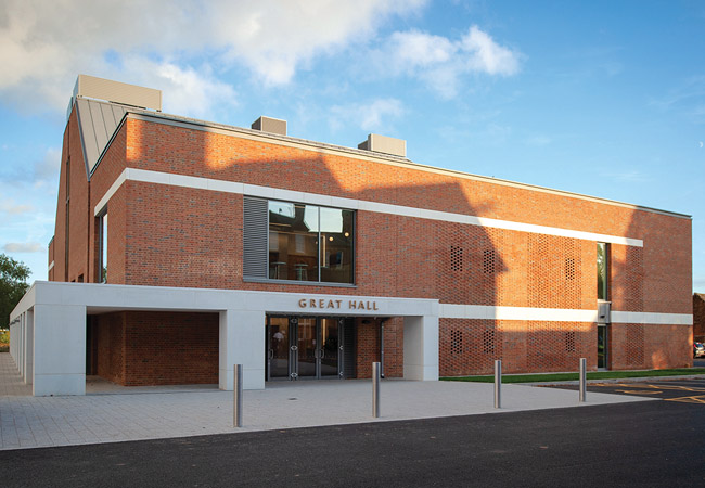
Kent College’s Great Hall
When James Staniland read about the use of an earth labyrinth at the University of Warwick’s Digital Laboratory, in the April 2012 edition of CIBSE Journal, he recognised the potential of the system to pre-cool large quantities of outside air without the need for mechanical cooling.
Eight years on, the practice of which he is a partner, Brinson Staniland Partnership (BSP), is using an earth labyrinth-type natural ventilation solution to help maintain comfort conditions in the Great Hall, at Kent College, Canterbury.
The Great Hall has been designed by architect HMY, working with BSP, to provide the college with a professional-quality performance space for musical and theatrical performances, and a facility for college assemblies. The 11m-high hall can accommodate up to 600 people seated in the stalls and first-floor circle.
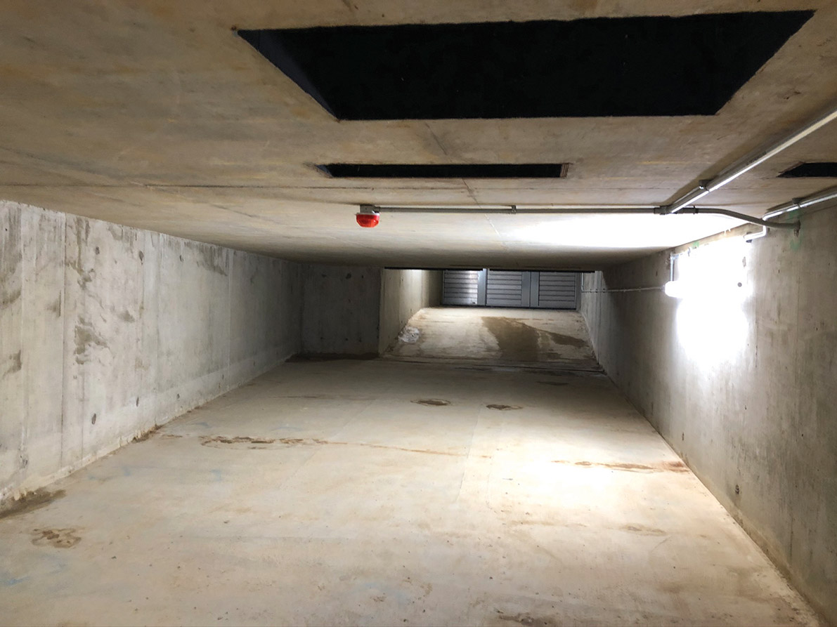
There are five giant concrete chambers
‘The two big driving factors that make this assembly space conducive to natural ventilation with labyrinth cooling are its considerable height and the high internal heat gains from the audience and from stage lighting and dimmer racks, which totals about 63.5kW,’ says Staniland.
Externally, the Great Hall’s brick walls and pitched, grey, standing-seam roof give it an understated appearance. It’s a theme that continues inside, with a relatively robust but aesthetic look derived from the exposed brick and timber finishes of the performance space. The hall is oriented on a north-south axis, with the stage to the south. Because it is a multi-purpose space, the envelope incorporates a significant glazed area, although the fenestration is concentrated mostly on the north and east elevations, where solar heat gains are less of an issue.
Earth ducts
The earth ducts are fundamental to the performance of the natural ventilation system to keep the hall comfortable in summer. Outside air enters the building from the south, through five giant, subterranean concrete chambers, each measuring up to 3.5m wide and 2m deep. The duct’s cross-sectional area has been designed large enough to allow the air to pass practically unimpeded.
‘With a natural ventilation system, you generally only have a maximum pressure of about 0.5Pa to play with,’ Staniland says.
In summer, the relatively constant temperature of the ground, at about 12°C, will ensure the chambers’ walls are maintained at a temperature close to that of the ground, to help cool the outdoor air entering the building. Dividing the intake into five separate ducts helps increase the area of duct in contact with the air, to maximise heat transfer, and helps with zoning the supply air. Each duct also incorporates a modulating motorised damper, to further control the quantity of outdoor air entering the space.
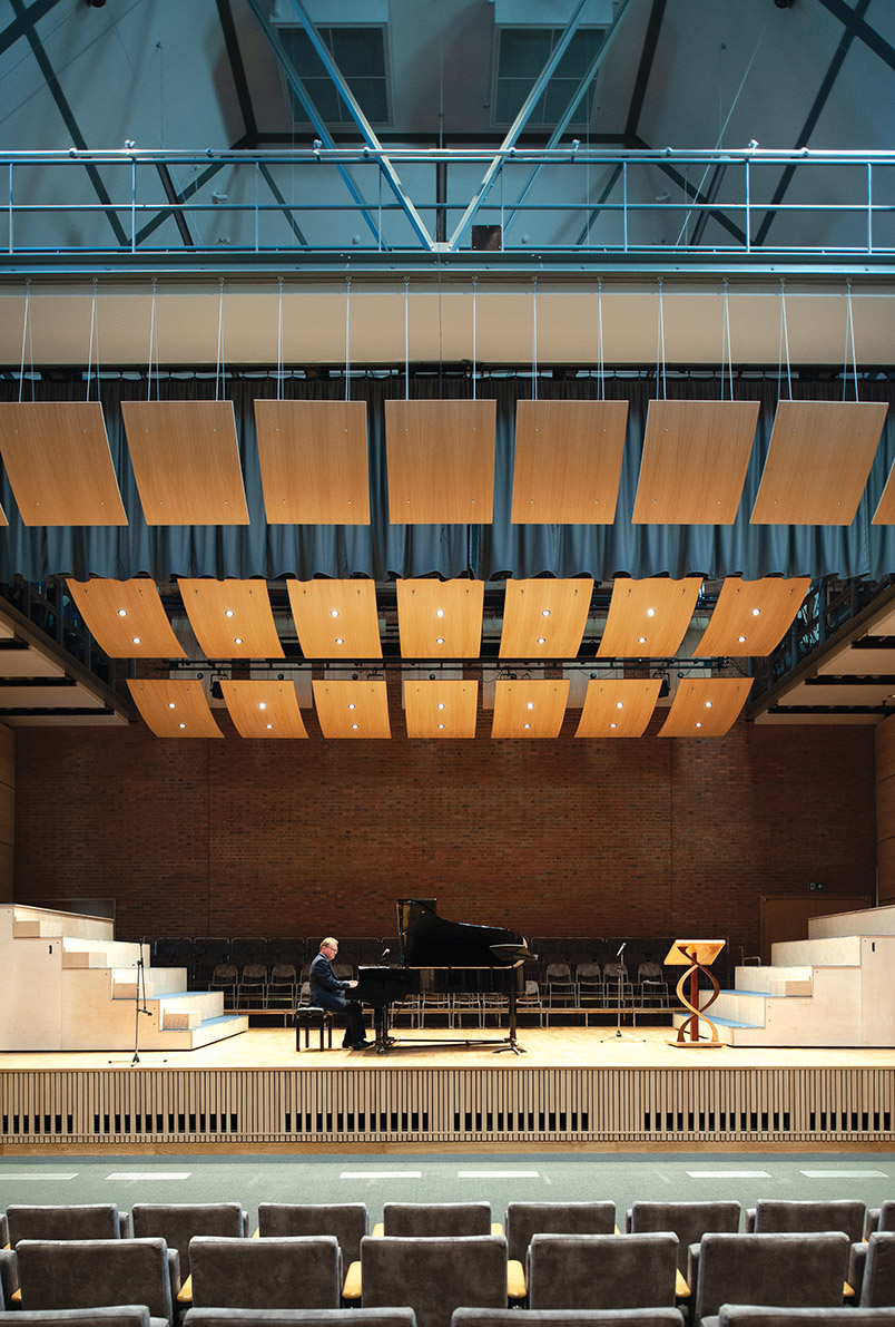
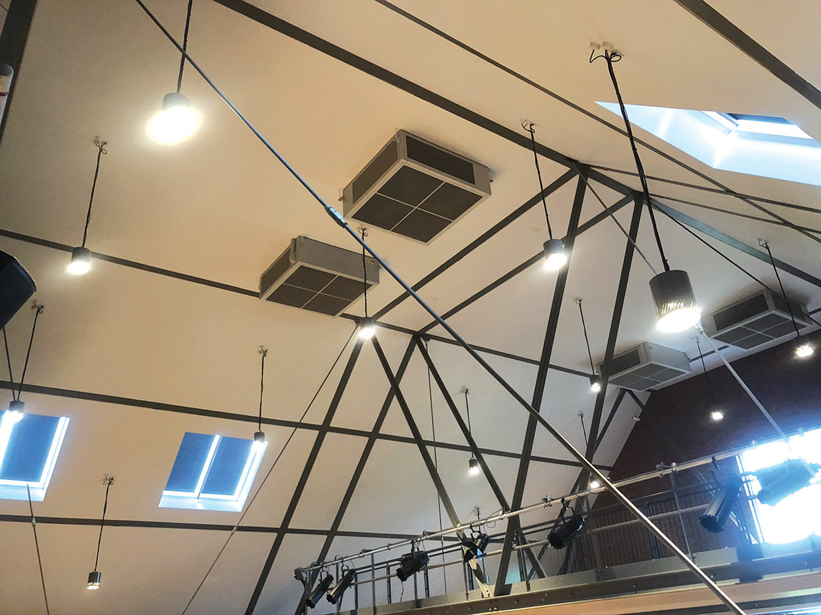
The Great Hall stage, which features MMV units at high level and sidewall supply grilles at the front
To maximise the rate of heat exchange with the chamber walls, the ducts have been sized so that the air flowing through them is moving just fast enough to enable it to turn from laminar to turbulent flow. ‘The flow turns to turbulent once it surpasses an air velocity of 0.014m.s-1 in the labyrinth, which it will do most of the time that the dampers are open, to maximise heat transfer,’ says Staniland.
The downside of ensuring a clear path for the air is that the concrete earth ducts present very little resistance to the passage of outside noise. Lining the concrete ducts with sound-absorbing material is one solution, but this would have limited significantly their ability to temper the outside air. Instead, the school has adopted the common-sense approach of ensuring its groundkeepers do not mow the lawns next to the air intakes when the hall is being used for performances.
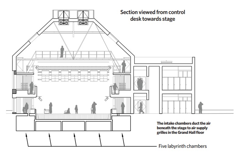
The five intake chambers duct the air beneath the performance stage to air supply grilles set into the hall floor and at low level in the auditorium walls. There is no high-level outdoor air supply, so – to keep the audience in the circle comfortable – its underside has been left open, and air can rise up and out through openings in the step risers beneath the rows of seats.
Buoyancy drives the vitiated air upwards to exit the hall through six roof-mounted ventilation units; these open up to act like chimneys when the building is in summer natural ventilation mode. ‘At the end of a hot day, the air just beneath the hall’s roof will be between 35°C and 40°C, making a significant contribution to the buoyancy forces,’ says Staniland (see panel, ‘Mixed-mode ventilation units’).
Modelling
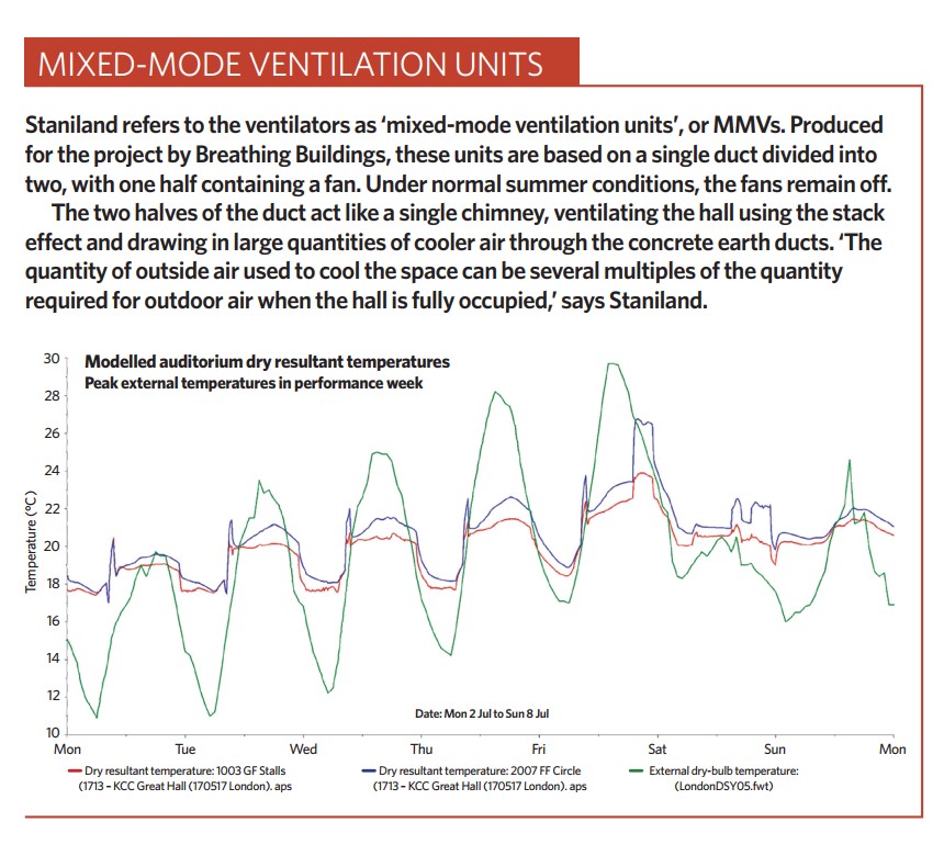
BSP modelled the scheme using dynamic simulation based on a week in July, when the weather is warm and the school will use the hall for a performance every day. ‘We decided that we would aim for a target dry-resultant temperature of 28°C at the back of the circle, which is the location of the highest audience seat,’ says Gearoid Donnelly, associate at BSP. The system worked; modelling showed that the temperature in this location would peak at 26.5°C, even on the hottest day, which Staniland says the team were ‘more than happy with’ (see Performance Week graph).
Once it is up and running, there is not a lot that can go wrong, because we’ve designed it to be simple to operate
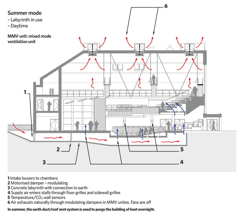
The same earth duct/roof vent system is used to purge the building of heat overnight. In late evening, the dampers in the earth ducts and mixed-mode ventilation (MMV) units open fully. Cool night air, at about 18°C, will pass through the building, removing heat from the intake ducts’ concrete walls and from the internal surfaces of the hall, including the exposed thermal mass of the hall’s fair-faced brickwork walls.
On summer mornings, school assembly will take place in the cooled hall. At this time of day, the system will operate under control of CO2 sensors, simultaneously modulating the dampers in the earth ducts and roof units to control the rate of airflow through the space. The system will operate in this mode throughout the day, remaining closed to keep the space cool and opening only when the auditorium is occupied and CO2 levels rise. The performance of the system was modelled using computational fluid dynamics at RIBA Stage 4, to show the space-temperature distribution and prove the effectiveness of the design.
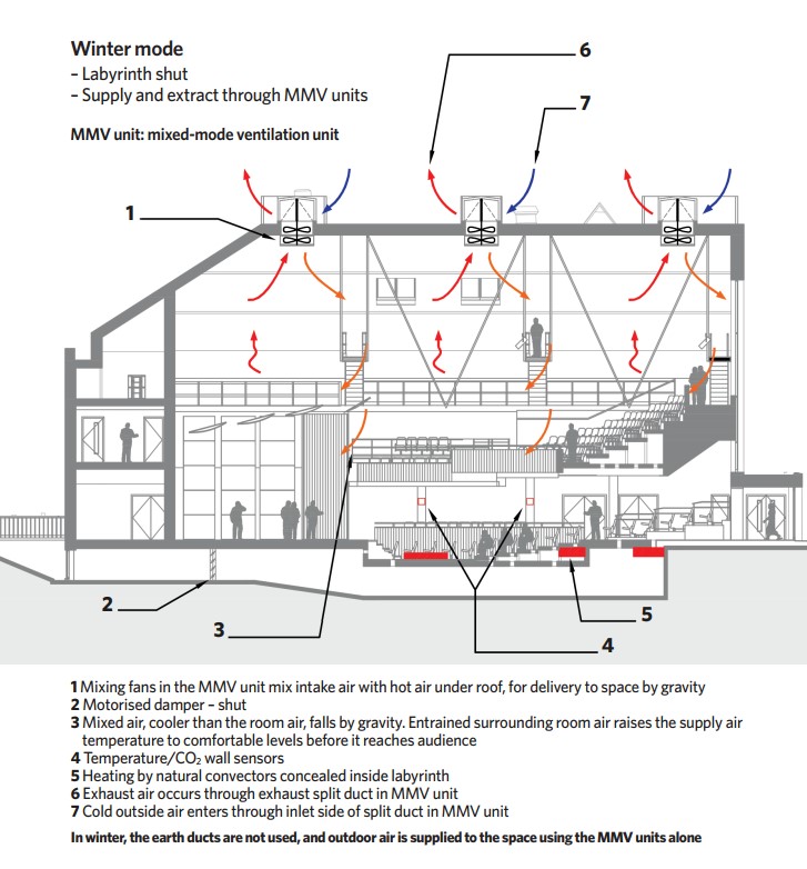
The earth ducts are not used in winter; instead, outdoor air is supplied to the space using the MMV units alone. In winter, theMMV units operate in one of two modes depending on the temperature of the outside air.
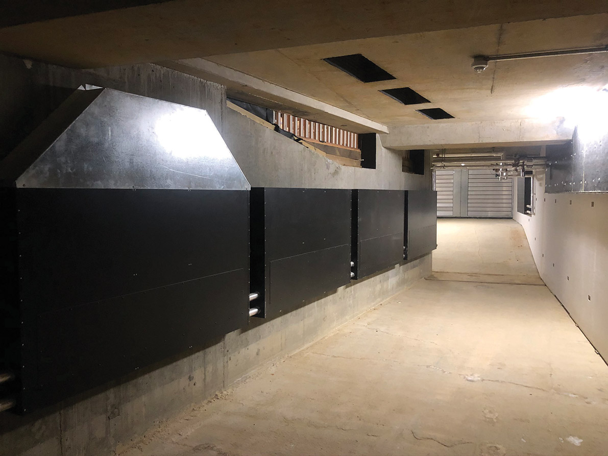
A labyrinth chamber during construction. Natural convectors in the foreground, modulating damper in the background, sidewall grilles in the side, and floor grilles overhead
When it is relatively mild, with an outside air temperature of 12°C or above, the fans in the MMV units will remain off. One half of the split duct will continue to operate as a chimney to exhaust warm stale air from the hall, while the other half of the duct will act as an outdoor air supply duct.
On entering the hall, the denser, cooler outdoor air will sink towards the floor. As it does so, it will mix with the warmed room air at a temperature of 35°C or so, trapped beneath the hall’s roof.
‘Through natural mixing, you are entraining the hot air in with the supply air, which is sinking under the pull of gravity, so you are making use of heated air that would otherwise have been wasted heating the roof,’ says Staniland.
‘By the time the cool air has reached the neck of someone sitting in the gallery, it will have entrained a significant amount of the surrounding air, so that its temperature will have increased to avoid causing discomfort,’ he adds.
In the second winter mode, when the outside air temperature is below 12°C, the fans in the MMV units will operate to help pre-mix the colder air with the warmed internal air, to prevent it creating cold draughts, without the need for pre-heat from the hall’s two small, wall-mounted, gas-fired boilers.
Heat is supplied to the hall in winter using a low-temperature hot-water system connected to finned natural convectors. These are concealed behind the same grilles that, in summer, are used to supply cooled air to the space; effectively the heating is hidden in the labyrinth supply air ducts.
Seasonal commissioning has been used to optimise the performance of the various systems. BSP is also monitoring the system remotely, in conjunction with the school’s facilities manager, to ensure it is operating effectively. Staniland says he would definitely do another earth-duct based scheme.
‘A system like this does require a certain amount of tweaking initially,’ he says, ‘but, once it is up and running, there is not a lot that can go wrong because we’ve designed it to be simple to operate.’
Project team
Client: Kent College, Canterbury
M&E Engineer: BSP
Architect: HMY
Structural engineer: CTP Consulting Engineers
Theatre specialist: Adrian James Acoustics
Project manager/QS: Fulkers Bailey Russell
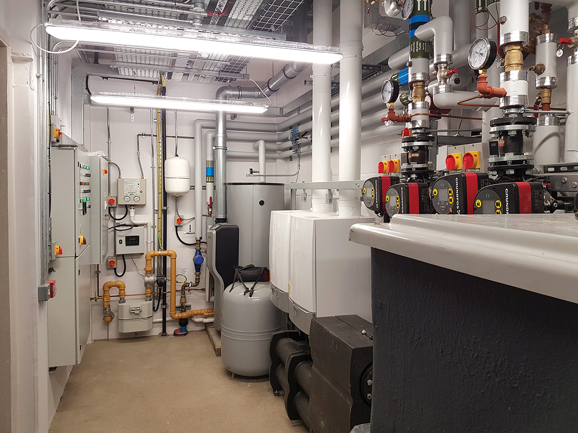
The modest boiler plant is evidence of significant fabric efficiency