‘The design adopts a fabric-first approach with passive design features to limit the demand on mechanical systems,’ says Tom Williams, associate at ChapmanBDSP. He’s talking about the Marshall Building, an 18,000m2 development for the London School of Economics (LSE), for which optimisation of form and fabric have been instrumental in minimising energy use.
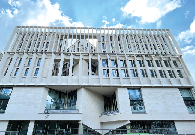
Designed by Grafton Architects, with ChapmanBDSP as MEP, sustainability and lighting consultant, the Marshall Building’s imposing Portland-stone façade faces onto Lincoln’s Inn Fields. Its lower storeys are clad in ashlar blocks interspersed with large, punched window openings, and, above, two successive layers of angled fins form an orthogonal stone veil in front of the glazing. The side and rear elevations are more fractured where they front the tight network of streets that make up the LSE estate.
ChapmanBDSP used daylight modelling and irradiation mapping to develop and optimise the façade design, and ensure access to natural light and fresh air. Its solar shading is designed to reduce solar gain and minimise summer overheating.
‘The ideal scenario in terms of reducing operational energy is to design the building to limit the amount of mechanical services we put into a space, introducing them only where they are needed to perform a specific function that cannot be achieved through passive means,’ Williams explains.
Behind the stone façade, the building is home to a multitude of functions. It houses lecture theatres, informal study spaces, academic offices, public spaces, music rehearsal and arts spaces, squash courts and a sports hall. These facilities are stacked vertically, from the sports hall and squash courts in the basement, through the Great Hall space on the ground floor, to the teaching spaces and lecture theatres on floors two and three, before finally rising to the research and departmental spaces – including the Marshall Institute that make up floors three to nine. ChapmanBDSP’s servicing strategy broadly reflects these four space types.
The most spectacular of the spaces is the expansive, dramatic entrance hall. Here, giant concrete, tree-like structural columns support the concrete mass of the building above. One of the columns even disappears through a void in the ceiling to support the floors above. A broad, curving concrete stair sweeps students up through a second void to the teaching spaces on the floors above. This huge ground-floor space, the Great Hall, is naturally ventilated. At one point, it was intended to be a semi-open piazza outside the building envelope, but as the design developed it, became incorporated into the occupied space, Williams says.
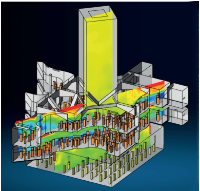
CFD analysis model with vertical section, showing temperature distribution
High-level openings in the exposed façades that enclose three sides of the hall allow fresh air to enter the space. ChapmanBDSP’s experience as engineers on naturally-ventilated buildings including the LSE’s Centre Building, completed in 2019 and which is almost entirely naturally ventilated, meant they were ‘confident’ in its application to the Great Hall, says Williams. The designers were helped by the building’s location in one of the quieter, less traffic-congested parts of London.
Actuators control the high-level openings based on temperature levels in the hall. ‘Openings either side of the hall allow for cross ventilation, taking advantage of a pressure difference between the façades,’ says Williams. ‘If the wind speed is high, then a connection to a weather station will prevent the windows opening,’ he adds.
In summer, the large, low-level windows can be opened manually to further link the space to the outside.
Radiant heat from a low temperature hot water (LTHW) underfloor heating system allows the space to remain comfortable in winter. The density of the underfloor heating is increased in non-transient spaces, such as the reception and cafe, to provide additional heat, while fan-assisted LTHW trench heaters adjacent to the glazed areas prevent cold draughts.
From the Great Hall, the sweeping staircase leads students up to the two teaching floors. Here, six Harvard-style, horseshoe-shaped lecture theatres – along with classrooms – are arranged around the floors’ perimeter, providing views out; the spaces in between are occupied by informal seating. The lecture theatres, which seat up to 90 people, are served by a displacement ventilation system. ‘These spaces are densely occupied so conditioning the fresh air supply is sufficient to heat and cool the space,’ explains Williams.
Conditioned fresh air is supplied to the void beneath the stepped, raked seating, from where it can permeate upwards through vents in the stair risers. ‘The building’s architectural intent was a driving factor behind the servicing strategies adopted throughout because Grafton’s style is bare, exposed concrete, without the services on display,’ Williams says. ‘The fact that you cannot see the mechanical services was one of the reasons behind the choice of displacement ventilation for these spaces.’
Variable air volume (VAV) terminal units in the underseat void regulate the amount of air entering each lecture theatre. The VAV units are supplied with fresh air through low-level ductwork in the floor void, supplied from one of two roof-mounted air handling units (AHUs). Air returns through open ductwork bellmouths at high level, concealed behind acoustic baffles. The ducts then drop to low level to be routed back to the main riser concealed in the floor void.
From a comfort perspective, displacement ventilation works with the supply air temperature close to room temperature, to prevent the feeling of cold draughts at the students’ feet. The system is controlled to prioritise the required volume of fresh air supply. In summer, if the VAV damper is fully open and more cooling is needed, the AHUs will decrease the supply temperature gradually in increments until it can meet the cooling demand.
Common spaces on the teaching floors are also conditioned using a displacement system, with the air load divided evenly between the two roof-mounted AHUs. Computational fluid dynamics (CFD) modelling was used to validate the heat-gain calculations and airflow rates for the displacement system (see panel, ‘CFD modelling’).
Floors three to nine are occupied by departmental and academic staff, housed mostly in cellular and group office spaces. These floors are sparsely populated in summer, so many areas are naturally ventilated without cooling. AHUs located on roof levels 9 and 10 supply tempered fresh air to these floors via vertical risers and ducts hidden in the floor voids.
In the group offices, the fresh air supply terminates at the rear of a four-pipe fan coil unit (FCU), also concealed in the floor void, to heat or cool the spaces. PIR sensors turn off the FCUs when spaces are unoccupied. Vitiated air is removed via an extract duct concealed in the floor void, which is linked to the AHU via the extract riser.
Concealing almost all of the services in the floor void was a big challenge, made more complicated by the void also having to contain cabling and wiring serving the concrete soffit-mounted services on the floor below. Services such as power to lighting and fire alarm cabling are sleeved through the slab to connect into the rear of the exposed soffit-mounted fixings. ‘In Revit, we had to coordinate the services while interfacing with the structural solution and the demands of the architecture,’ recalls Williams.
CFD Modelling
CFD modelling was used to validate chapmanbdsp’s heat-gain calculations and airflow rates for the displacement system. These assumed that some heat gains do not fully impact the occupied space, such as heat gains from lighting. ‘A proportion of the heat gain from the lights influences the occupied zone, but a lot of heat is almost instantly extracted from the space at high level,’ explains Williams. This approach enabled chapmanbdsp to apply weighting factors to the different heat gains within a space, to refine the amount of air provided by the displacement system.
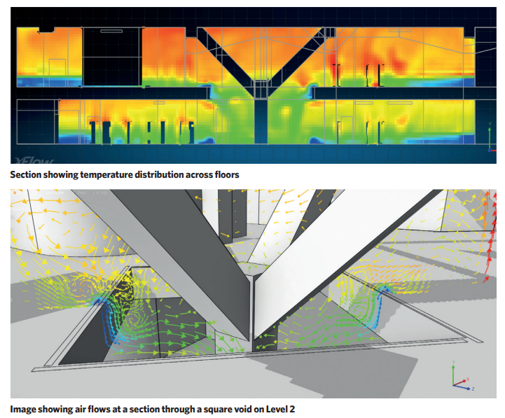
chapmanbdsp also used the CFD model to prove exhaust air at high level could pass the downstands formed by the tops of the structural trees, and also to assess the extent to which air could drop through the two open voids in the teaching floors to the Great Hall below.
‘We had a scenario where the teaching spaces are served by displacement ventilation, with a large void to the naturally ventilated ground floor entrance hall. We were interested in potential air transfer between the two spaces, and ways in which we could prevent this,’ says Williams.
Modelling showed that, if the vents were open on the ground floor, there would be a rush of air down and out of the building, and even if the vents were closed, the relatively cool air from the first and second floors, at approximately 19°C, would still sink down through the voids, depriving the first and second floor occupants of the benefit of cooling.
‘As a result of the CFD modelling, we extended balustrades around the void to floor level to contain the cooled air,’ Williams says
A benefit of having so much exposed concrete is being able to exploit its thermal mass. ‘A lot of systems run with a night-purge function to use the thermal mass to its fullest extent to absorb heat during the day and then flush it out at night,’ Williams explains.
The roof-mounted AHUs also provide ducted tempered fresh air to the cellular offices. Ducts terminate at passive trench-heating units where, in winter, the LTHW coil provides heat to the offices. Thermal comfort in these spaces mid-season and in summer is from occupants opening the windows.
The rooms have been tested, using CIBSE TM52, to ensure they will not overheat. In response to climate change, or after a change in use, FCUs can be added to the floor voids in the cellular spaces for more cooling. The main water-cooled chiller plant is in the basement, with adiabatic dry coolers for heat rejection on the roof. The chiller has been designed to accommodate this potential additional load, based on average occupant density across the floor being one person per 8m2.
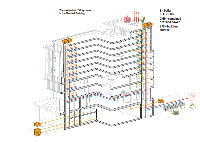
Heat is provided by gas boilers in the basement plantroom. When ChapmanBDSP first conceived the system, it included a bio-fuelled combined heat and power (CHP) engine intended to form part of a campus-wide energy network.
However, with the decarbonisation of the electricity grid occurring over the life of the project, and a move towards all-electric buildings, the energy network is no longer proceeding and the CHP option was scrapped in favour of standalone gas boilers.
‘If the project were designed today, the central energy strategy would reflect an all-electric approach with the use of heat pumps to maximise the benefit of lower carbon electricity,” says Williams.
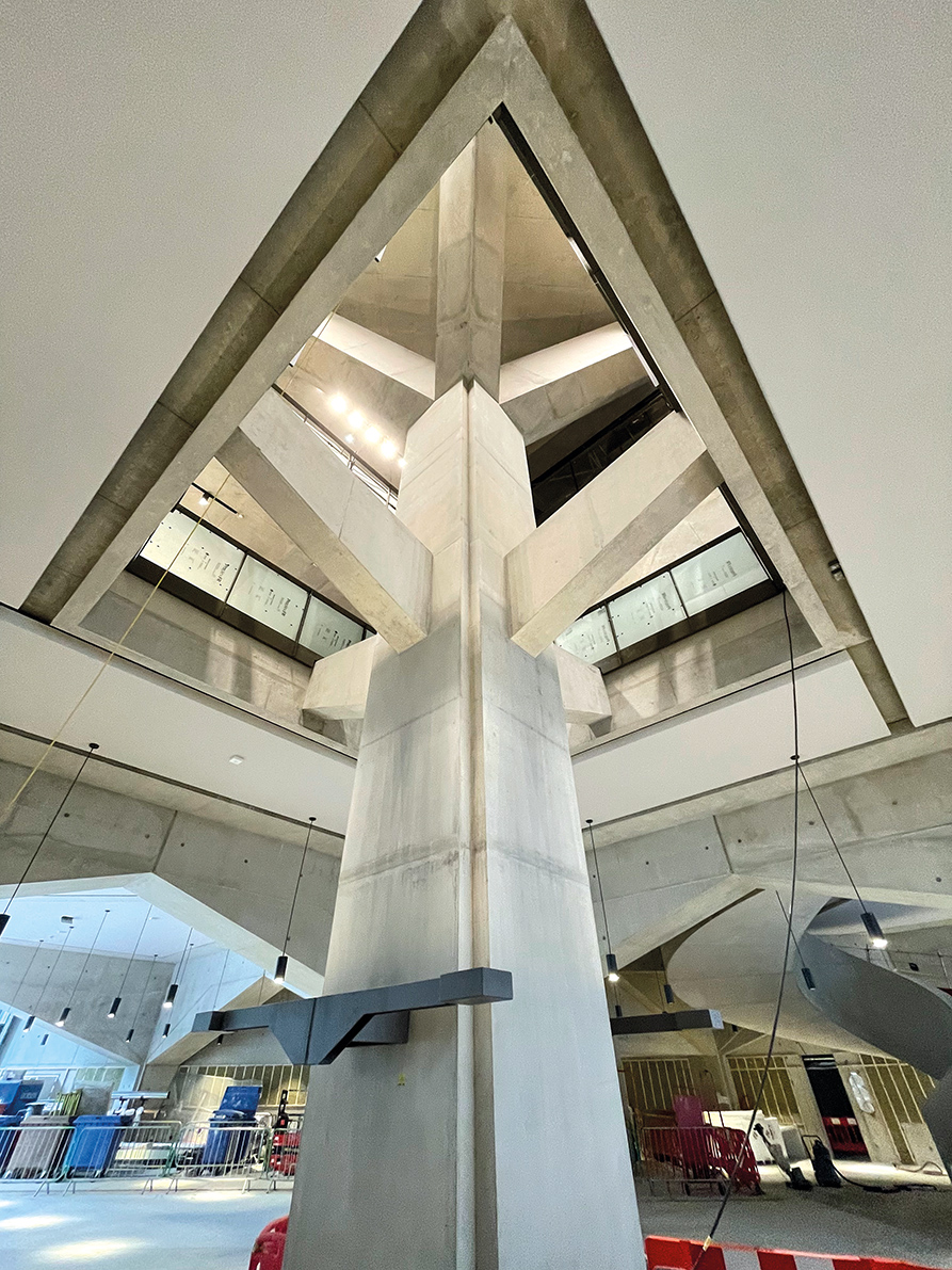
One of the giant, tree-like columns in the Grand Hall
The basement is home to a 20m x 35m x 7.5m-high sports hall, two squash courts, gym, and music rehearsal facilities. A VAV system from a dedicated AHU serves the sports hall and squash courts, with a second AHU serving remaining spaces. ‘Because of the size of the sports hall, and the amount of fresh air we are putting into it, the ventilation can also be used to heat and cool the space,’ Williams explains.
A unique feature is a special button on the BMS that enables the sports hall’s ventilation system to be turned off. This ensures compliance with a Sports England requirement that elite-level badminton courts do not have forced air movement, as it might affect the flight of the shuttlecock. It is probably the one passive design feature that ChapmanBDSP failed to anticipate.