This part of the guide to combined heat and power (CHP) efficiency looks at thermal stores, the control of heat injection, and the factors affecting sizing. The first article (A condensing guide to CHP efficiency, CIBSE Journal, November 2019) analysed different design configurations of CHP, the detrimental effect on performance of pre-heat designs (CHP in series return with boilers), and the advantages of four-pipe and two-pipe thermal store configurations.
To optimise a CHP’s thermal and electrical capacity, it’s essential to understand the building’s profile and base load through dynamic building simulation or hour-by-hour calculation – and by considering how a thermal store or buffer vessel is to be used. Having a properly designed thermal store allows the CHP to provide thermal space for discharged heat and give a volume of heat that can be injected into the system when the CHP is at 100% output, reducing boiler firing time.
Thermal store
A thermal store stratifies a thermal layer, offering usable heat at the same flow temperature as the heat source. When heat is required, fluid is removed from the warm layer on the top of the store. Under steady-state conditions – where heat in = heat out – the thermocline layer is static.
A well-stratified, charged tank can have thousands of litres of water at system flow temperature (or greater), which can inject heat into the system when the CHP is at maximum load. This will delay the boilers from firing, allowing peak demands greater than CHP maximum thermal output to be satisfied.
A thermal store can also provide heat if the system’s output is less than the CHP’s minimum downturn. This principle applies if the thermal load is small compared with the electrical requirements.
In both cases, some manufacturers use a dry-air cooler to dump heat to atmosphere, a practice that Remeha cannot condone. In both examples, the thermal store capacity and charge status dictate how long the boost and alternate thermal path functions can operate.
Buffer vessel
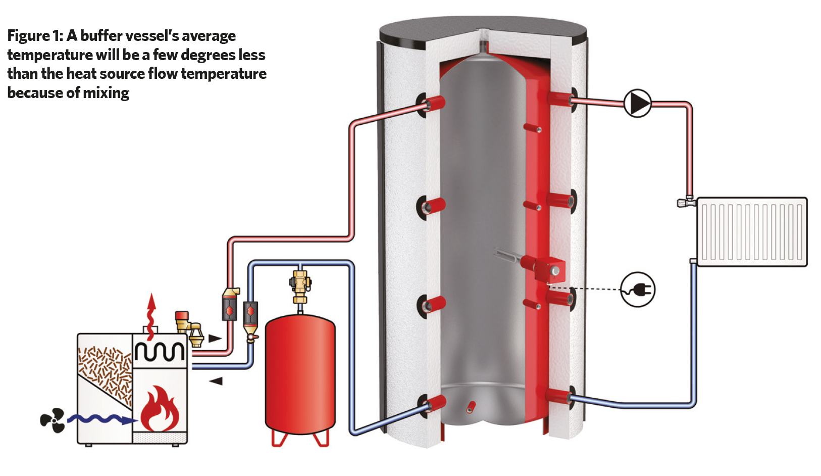
The average temperature of a buffer vessel will be a few degrees less than the heat source flow temperature because of mixing. While it can be used for the same tasks as a thermal store, the usable energy will always be less because of the exergy within the non-stratified tank. The exergy influences how much the stored energy can effect a change to its surroundings.
When designing or specifying a thermal store, we recommend adding sparge pipes or diffusers to minimise internal mixing, which can ruin the thermocline layer. Particular attention should be paid to velocities entering the tank, no greater than 0.15m/s.
Topping the peaks
First, decide whether the CHP should be thermally or electrically led. Many design guides offer advice on how to choose the primary control philosophy, so the focus here is on the discharge side.
The modified parallel arrangement (four-pipe configuration) in Figure 1, explored in part one, introduced the concept that the discharge pump (B) actively controls the tank charging (energy in > energy out), discharging (energy in < energy out) or equilibrium (no net change in energy). The correct flowrate (Q) sizing of pump (B) is key to the success of modern CHP design. If (QB) > (QA), the store will discharge while the CHP is running, increasing the peak output of CHP-generated heat into the building.
The heat injection is a finite function of volume store – and the store must not be fully depleted, as this can cause mixing. However, this safe volume percentage discharge limitation can be overcome using a two-port store, as outlined in part one, but at the expense of a more constrained installation.
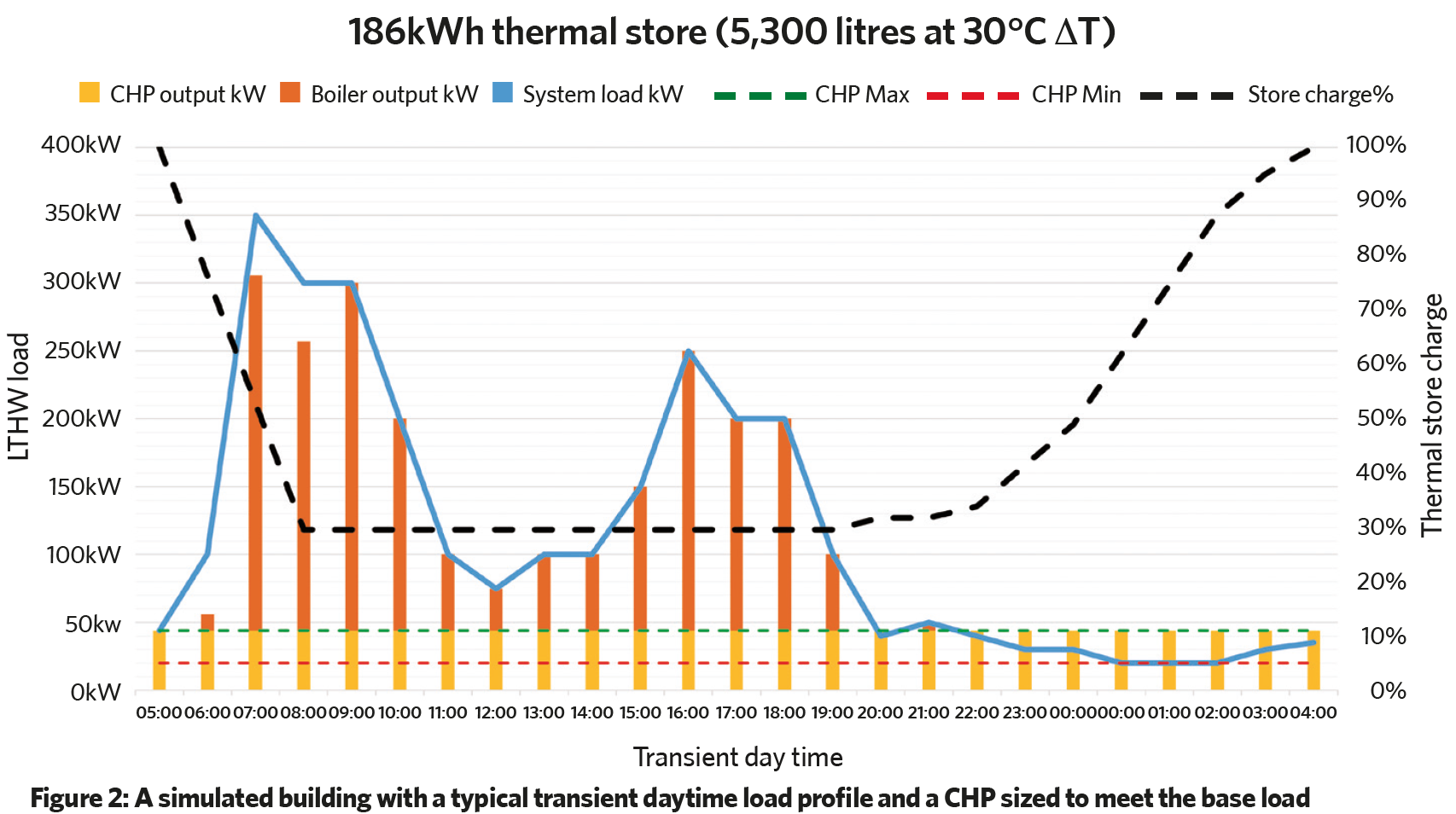
Figure 2 is for a simulated building with a typical transient daytime load profile and a CHP sized to meet the base load. By 5am, the store has been fully charged by the CHP. At 6am, the thermal store’s energy is released to assist the CHP in meeting the peak, while the boilers do not fire. At 8am-9am, the BMS sees that the tank has reached its safe-percentage depleted levels by monitoring temperature sensors. QB is reduced to match QA, bringing the thermal store back into equilibrium.
This continues until 7pm, when the load drops off and the CHP starts to recharge the store. The heat demand is less than the CHP output and, now, QB < QA. The CHP continues to run at full output, charging the store overnight.
This example assumes an electrical base load, equal to the CHP maximum output, that is always used by auxiliary, small power and lighting loads, or exported to the grid.
Boiler firing and cascading should be achieved using flow and return temperature sensors on the system side, as well as on the thermal store flow. If the store’s safe-discharge percentage has been exceeded and the output temperature is less than the system set point, a temporary increase in boiler flow temperature should be used to regain the system set point temperature. We strongly advise that an allowance is made for iterations on the BMS set points and timings, to achieve the best results across seasonal commissioning visits.
Sizing the thermal store
CIBSE AM12 states that to establish the optimum size of the store, it is necessary to use an hour-by-hour operating model, preferably for the whole year, and to carry out a series of calculations with a range of store sizes. The size of the thermal store affects the system’s ability to hold off the boilers.
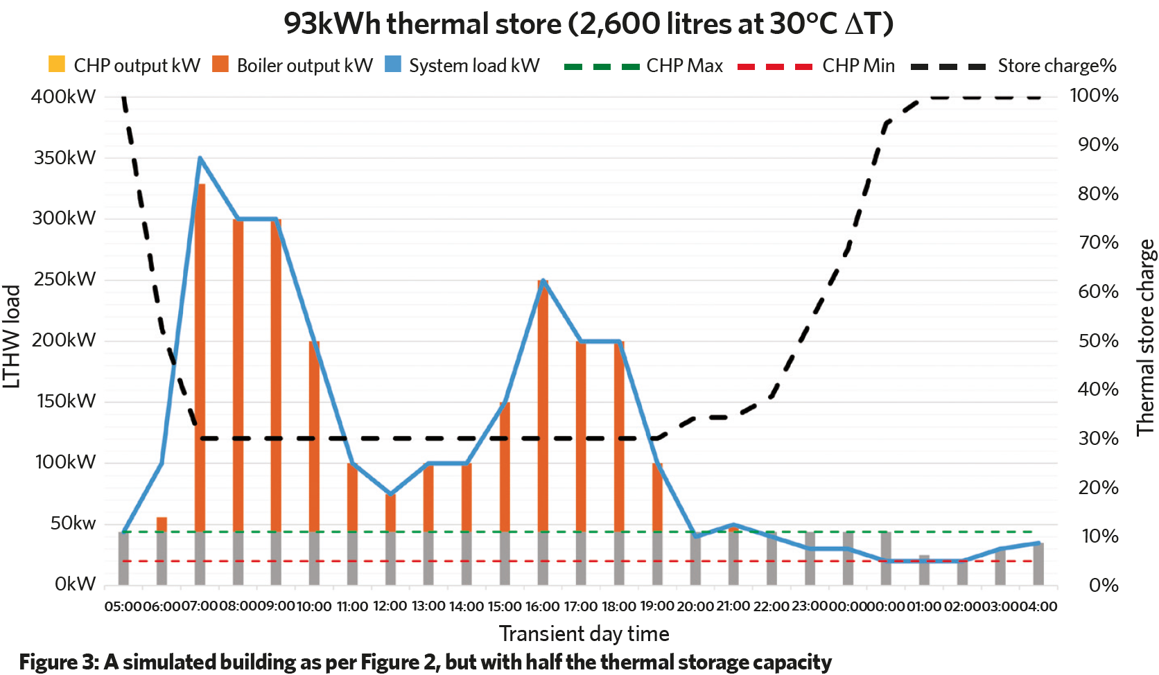
Figure 3 shows the same building profile as in Figure 2, but with a store of half the thermal capacity. In this example, the boilers are used more in the morning (start-up) to meet the demand, and the store charges very quickly. This reduces the CHP’s ability to run on full output overnight and requires the CHP to turn down to just above minimum output. A store sized for the full CHP thermal output overnight will always be favourable, but to ascertain the optimum store size for your project, consider:
- Plant area and height restrictions
- Typical winter, summer and transient day loads for electrical and thermal demands
- The size of CHP required for base load and the size proposed (oversized to meet compliance, for example)
- Building load profile/use.
As CIBSE guidance suggests, modelling the proposed configurations will help with understanding of a system’s performance and outline the control philosophy required to maximise use of the CHP’s generated heat.
About the author
Ryan Kirkwood is specification manager at Remeha