With the evolving complexities of heat generation, and the need for correct and efficient operation of both heating and cooling sources, it is important to design and integrate headers correctly into systems.
This article aims to provide definitive design guidance and more detail than has previously been published on the subject. It follows ‘Talking headers’, February 2014, CIBSE Journal, which covered key design considerations for headers and flow regimes within headers. This resulted in queries about headers design and the calculation of parasitic flow in offline load circuits: this article sets out to cover both areas.
What is a low loss header?
A widely accepted definition of a low loss header (LLH) is a device that provides hydraulic separation between separately pumped primary and secondary circuits. Hydraulic separation means that primary/secondary pump interactions are avoided, with primary/secondary pumps operating independently of each other. For this reason, they are also known as hydraulic separators – but while a LLH provides hydraulic separation, a hydraulic separator is not necessarily a low loss device.
Considerations for designing a low loss header are:
- The need for a very low pressure drop along the header to achieve low pressure loss mixing of primary and secondary flows
- The relative locations and sizes of the primary and secondary ports
- The minimising of parasitic flows in offline load circuits.
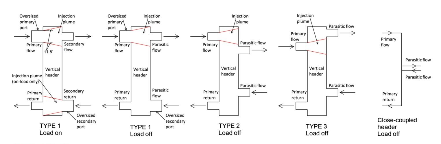
Figure 1: Types of low loss headers
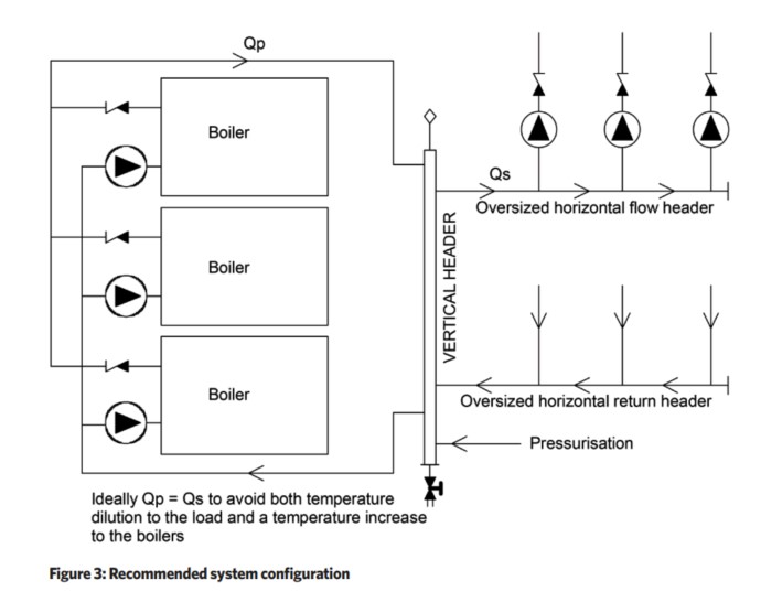
Achieving a very low header pressure loss is a straightforward calculation, while the locations of ports depend on whether the design is principally for primary flow (Qp) greater than secondary flow (Qs) or vice versa. Ideally, Qp=Qs, but this is difficult to achieve in practice. Temperature dilution to the load will occur when Qs>Qp, which could impact on, for example, air handling units that require a minimum flow temperature to operate correctly.
Alternatively, a temperature rise to the boilers’ return will occur when Qp>Qs, preventing boilers from condensing if the load circuit is designed for a return temperature <55°C. Optimising hydraulic separation and minimising parasitic flow is the primary focus of this article, using type 1 or type 2 headers (Figure 1), as perfect hydraulic separation is not achievable in practice.
Oversizing the primary and secondary flow ports will optimise hydraulic separation and minimise parasitic flow by reducing the injection velocity into the header
Calculation of parasitic flow
The calculation of parasitic flow in an offline load circuit requires the pressure drop developed on the header between the secondary ports (both type 1 and type 2 headers) to be considered as a pressure source that creates a flow in the offline load circuit. In addition, a component of dynamic (velocity) pressure from the primary flow entering the secondary flow port from the primary injection plume has to be included in the calculation for type 1 headers.
Oversizing the primary and secondary flow ports will optimise the hydraulic separation and minimise the parasitic flow by reducing the injection velocity into the header.
An iterative solution was developed whereby the header diameter, the spacing between the secondary ports, and the full-load pressure loss of the load circuit can be varied to achieve a balance between the pressure developed across the header and the off-load pressure loss of the load circuit, for boilers and loads from 50kW to 3MW and at flow temperatures from 40°C to 120°C.
Example calculation
Take a system with a primary circuit rated at 400kW, operating at 80°C/60°C, connected to a 350kW load circuit via a 150mm header with 500mm secondary port spacing. Figure 2 shows the parasitic flow in the load circuit for primary flow port sizes of 65mm, 80mm and 100mm versus load circuit full-load pressure loss (solid lines).
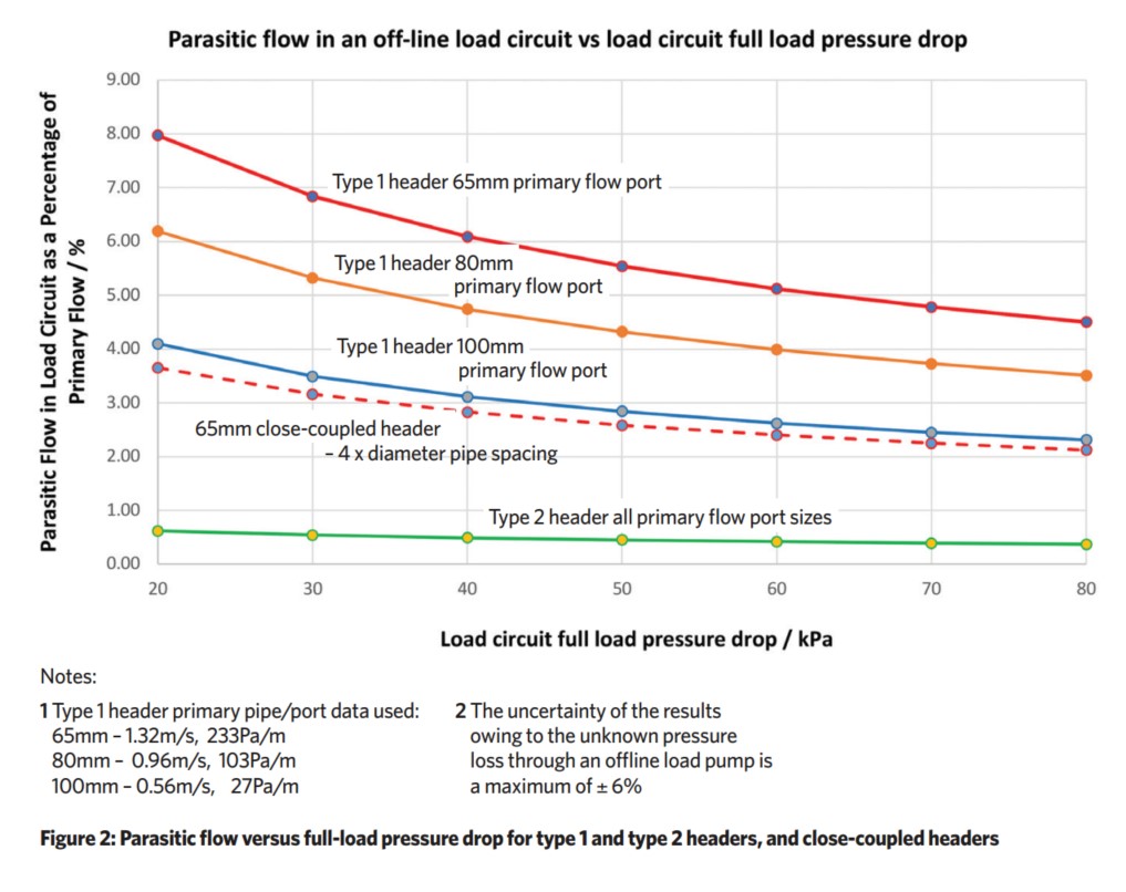
The smaller the primary flow port, the greater the injection velocity into the header and the greater the pressure exerted onto the secondary flow port. Oversizing the primary flow and secondary return ports, and lead-in pipes, will optimise hydraulic separation and minimise parasitic flow.
Close-coupled headers
Close-coupled headers (CCHs), as widely used in the USA, can be evaluated by setting the header and primary pipe diameters to the same size in the tool. The dotted red line in Figure 2 shows the parasitic flow resulting from secondary pipes spaced four pipe diameters apart on 65mm primary and secondary pipes. However, CCHs do not meet the definition of a LLH because any flow mixing is not low loss. They are not the same as a LLH, and should not be used in lieu of a LLH, but CCHs can be useful when injecting heat – for example, a combined heat and power output – into a primary circuit.
Uncertainties
- No information could be found to quantify the effect of offline pumps on parasitic flows. There will be a minimum ‘striking’ pressure (Psmin) before an offline pump begins to freewheel, below which there will be no parasitic flow. Furthermore, the pressure losses through an offline pump are unknown.
- Injection plumes are shown in the headers in Figure 1, and further information is sought on the penetration of the primary flow into and through the header, specifically velocity versus distance profiles when the majority of flow is running at right angles down the header.
Surface roughness
The pipe pressure loss tables in CIBSE Guide C do not provide any information on the likely increase in pipe pressure losses over time. For the example calculation, while a header using new steel pipe will have a pressure loss of 3.65Pa.m-1, a corroded pipe will have 5.26Pa.m-1, and a badly corroded pipe 11.78Pa.m-1. It is important to maintain water quality for the life of a system to maintain the low loss properties of a header over time.
Recommended system configuration
Figure 3 shows a recommended configuration for a generic system. The use of a type 2 header effectively eliminates parasitic flows, and if – as is likely – Psmin is greater than the static pressure difference across the secondary ports, parasitic flow will not occur.
The pressure developed across the load circuits by a type 1 header when off-load is greater, although still relatively small – a few hundred Pa at most. However, when on-load, a type 1 header does not provide hydraulic separation, as the primary has the potential to pump into the secondary and then back into the primary.
Installing non-return valves (NRVs) in series with each secondary pump has the potential to eliminate parasitic flows, providing the pressure required to open the NRVs is greater than the pressure imposed by the header across the load circuits. CJ
UPDATED DESIGN RULES
The following revised and expanded design rules should achieve good hydraulic separation and minimise parasitic flow in offline load circuits:
- Rule 1. On type 1 and 2 headers, ideally Qp=Qs, but Qp>Qs to prevent temperature dilution to the load or Qs>Qp to avoid a temperature increase to the boilers
- Rule 2. A type 3 header is preferred for constant return temperature Qs>Qp, and with the secondary flow port located above the primary flow port
- Q Rule 3. Oversize the primary flow and secondary return ports on type 1 headers, together with lengths of pipe 5-10 times the diameter of the ports on the inlets to each port, to achieve a pressure loss <100Pa.m-1.
For all types of header:
- Rule 4. The flow velocity and pressure drop along the header should not exceed 0.3m.s-1 and 5Pa.m-1 respectively at boiler outputs up to 3MW
- Rule 5. The LLH diameter is likely to be a minimum of twice that of the primary flow and return pipes for a boiler output of 3MW, and up to three times that of the primary pipes at 50kW
- Rule 6. The physical distance between the secondary ports is a minor consideration if a header conforms to Rules 4 and 5
- Rule 7. The header should be mounted vertically to trap sludge at the bottom and permit air removal at the top
- Rule 8. The header should operate at neutral pressure with the suction (inlet) side of all pumps connected to the header
- Rule 9. System pressurisation should act directly onto the header
- Rule 10. Maintain water quality for the life of the system.
■ The Low Loss Header calculator, currently in the form of a non-peer-reviewed research tool, can be downloaded from the CIBSE Journal site at bit.ly/LLHcalc
■ Any reader with quantified information on injection plumes, the striking pressure and losses in offline centrifugal pumps, or with comments on the calculator, is asked to post their response (with subject line: Low loss header) to editor@cibsejournal.com
■ Ryan Kirkwood is the heat pump business development manager for Baxi Heating
David Palmer is now retired. He was formerly a director of the Campbell Palmer Partnership