

Focus on whole life carbon (WLC) has increased significantly in recent years, with the aim of reducing the environmental impact of the built environment and driving towards net zero carbon.
WLC encompasses the emissions from the operation of the building and the embodied carbon of the materials.
Operational energy is generally considered to be well understood and, in recent years, there has been a growing focus on the embodied carbon of a building.
Initially, a lot of this was targeted at structural elements, such as the concrete or steel frame, as this typically contributes the largest proportion of embodied carbon emissions. In a net zero carbon future, however, the industry will move away from new builds and towards major refurbishments, so the internal fit-out of a project becomes a significant proportion of the embodied carbon.
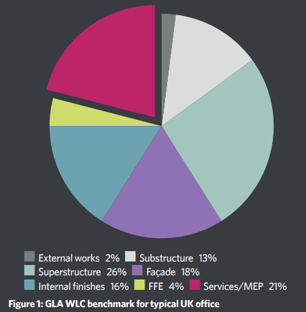
As an item that is replaced regularly during a building’s life, and that is directly linked to operational energy consumption and fugitive emissions (refrigerant leaks and irregular releases), building services can have a major impact on the WLC of a development. The recently released Greater London Authority (GLA) WLC benchmarks for a typical office clearly demonstrate this, with the services accounting for 21% of the total.
Recently, CIBSE published TM65, which made the task of estimating embodied carbon in building services much more accessible. In an effort to contribute to this field, this study quantifies the WLC of three options for typical office heating and cooling systems: air source heat pump (ASHP) four-pipe fan coil unit (FCU); variable refrigerant flow (VRF); and hybrid-variable refrigerant flow (HVRF) (see panel, ‘Systems in the study’).
The study is based on an eight-storey office block comprising two tenancy splits per floor, providing about 12,500m2 of commercial office space. For each system, the following items have been included in the scope of the analysis: central plant (ASHP or external condenser); refrigerant; energy consumption; FCUs; distribution and condensate pipework; pipework suspension, fittings, and insulation; pumps; buffer vessels; branch controllers; and secondary ductwork and grilles.
As an item that is replaced regularly, building services can have a major impact on the WLC of a development
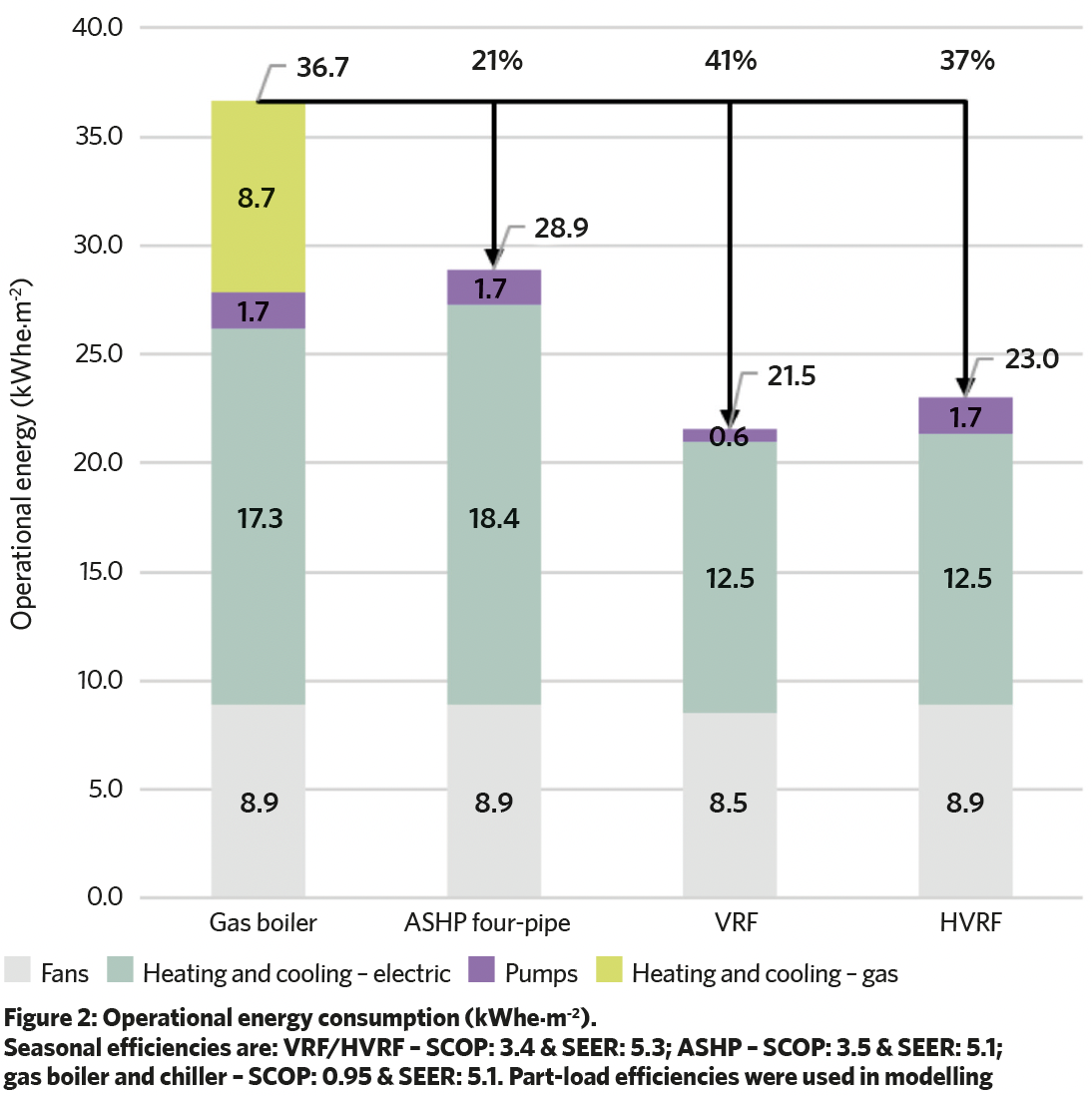
The operational energy performance of each system has been estimated using IES-VE ApacheHVAC software, and the resultant annual energy consumption, in kWh.m-2, is reported for the fans, heating and cooling equipment, and pumps in Figure 2.
For reference, a gas boiler baseline scenario has been modelled. The study concluded that the VRF system is the most efficient of the three, at 21.5kWh.m-2, then the HVRF at 23.0kWh.m-2 and, finally, the ASHP system, at 28.9kWh.m-2, with all showing a reduction over the gas boiler baseline.
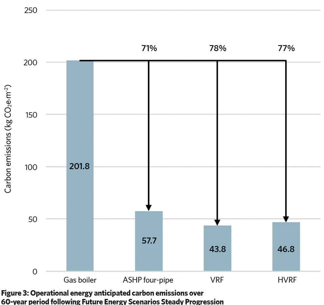
In Figure 3, the energy consumption of each system has been converted to carbon emissions, analysed over a 60-year period, by mapping against the Future Energy Scenarios (FES) Steady Progression carbon trajectory. As with the energy consumption, the ASHP performs the worst, with the equivalent emissions being 58kg CO2e.m-2, compared with 44kg CO2e.m-2 for the VRF system and 47kg CO2e.m-2 for the HVRF system.
However, because of each of the systems benefiting from a decarbonising Grid, a significant reduction for all three cases is seen against the gas boiler baseline, which has a carbon impact of 202kg CO2e.m-2.
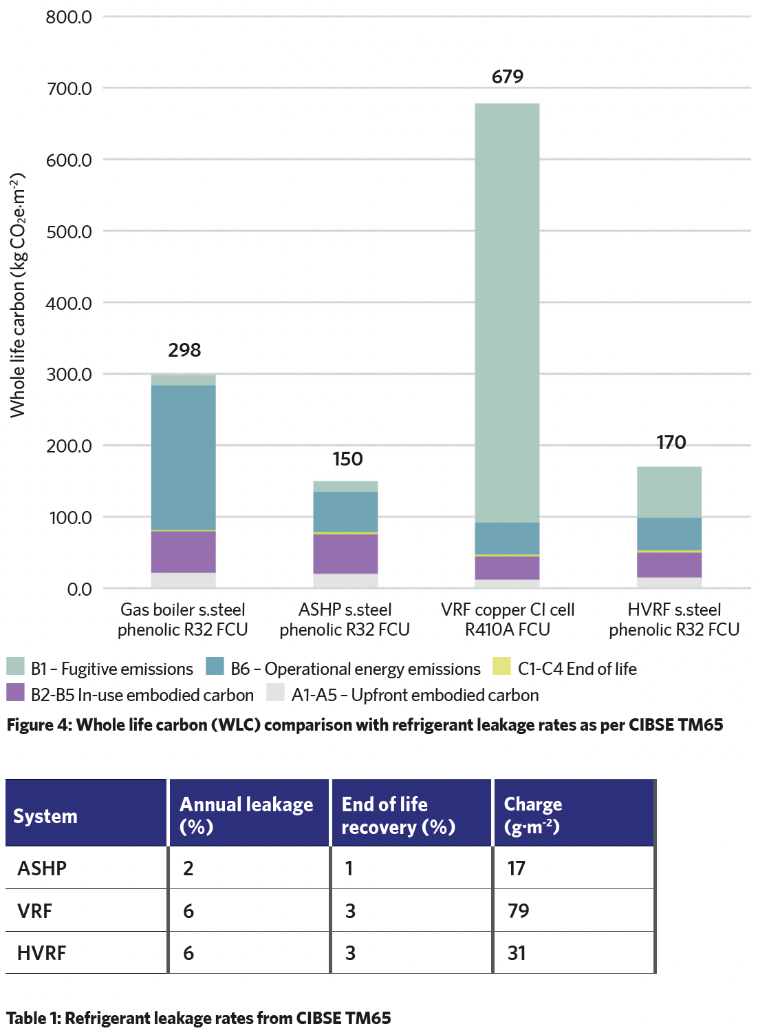
The embodied carbon of the materials/components in each system has been assessed using a combination of Environmental Product Declarations and CIBSE TM65 calculations. The results have been added to the operational energy emissions in Figure 4, representing WLC for each system, with the results split by life-cycle modules A-C, in line with BS 15978.
The refrigerant leakage (module B1) has been assessed using the leakage rates provided in CIBSE TM65 (see Table 1) and this has a significant impact on the results of the systems, which include refrigerant distribution, particularly VRF. This increases the impact of the VRF to 679kg CO2e.m-2, making it the worst performing, and more than twice as harmful as the gas boiler equivalent.
When the refrigerant leakage is not accounted for, the operational energy emissions (module B6) for the ASHP, VRF and HVRF systems equate to approximately 50% of the WLC, as opposed to 70% in the case of the gas boiler.
Three main factors contribute to the impact of the refrigerant: the total system charge, the global warming potential (GWP) of the refrigerant, and the leakage rate.
It is the combination of these factors that result in a significant impact on the VRF system when refrigerant is added to calculations. The VRF system has the highest refrigerant charge, it typically uses high GWP refrigerants, and it has a higher leakage rate.
As it is not possible to affect the total charge without changing the system, strategies to reduce the impact must come from influencing the refrigerant GWP and leakage rate. The ASHP and HVRF systems already use refrigerants with a lower GWP, but this is not currently feasible for the VRF system. Such refrigerants are more flammable and, so, not commercially available for use within occupied areas under BS EN 378 Operational use and safety requirements. For reference, R32, used with the ASHP and HVRF, has a GWP of 675kg CO2e.kg-1 compared with the R410a’s GWP of 2,088kg CO2e.kg-1 in the VRF system.
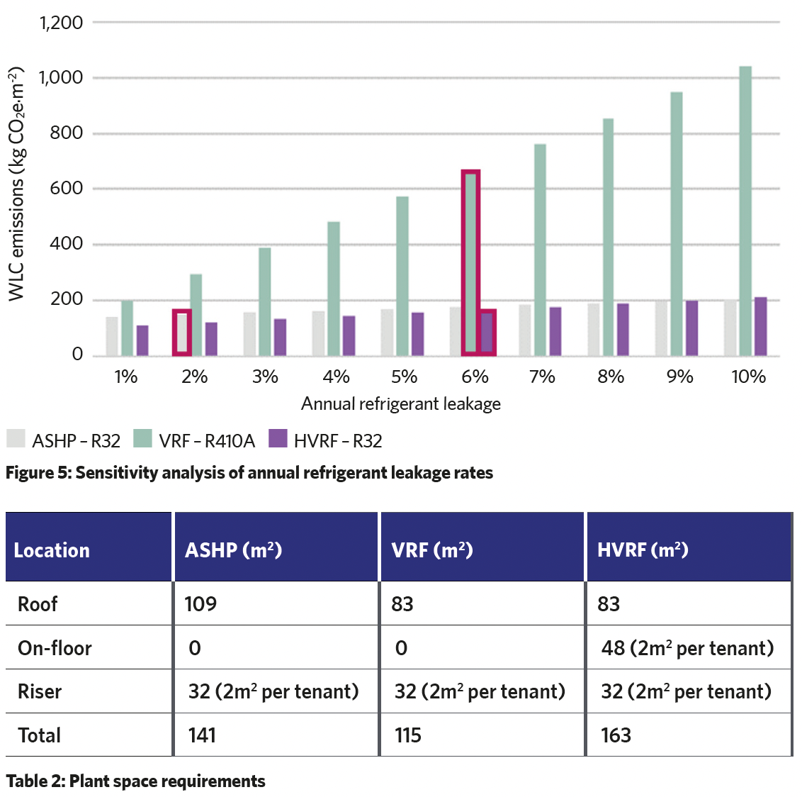
Figure 5 demonstrates the impact of changing the assumed refrigerant leakage rate – with the scenarios as per the CIBSE TM65 recommended rates highlighted. This shows that significant reductions can be realised by reducing the leakage rate of the VRF system, but this has to be reduced to less than 2% for the resultant WLC emissions to be lower than for the gas boiler.
It would only be possible for the system to be similar to the ASHP and HVRF if the refrigerant was changed to have a GWP comparable with R32, and limiting the annual leakage rate to below 2%.
In addition to the WLC impact, the study explored other factors that play a part in system selection, including plant space, whole life cost, and thermal comfort.
Systems in the study
Air source heat pump (ASHP) four-pipe fan coil unit (FCU)
ASHPs are mounted at roof level, and low-temperature hot water (LTHW) and chilled water (CHW) pipework is distributed from the roof to each of the office floorplates via risers in the cores. LTHW and CHW pipework is then distributed at high level on each floorplate to FCUs. There are three ASHPs supplying heating and cooling to the whole building in a duty/duty/assist arrangement. The ASHPs contain a much lower charge of refrigerant compared with the variable refrigerant flow (VRF) and hybrid VRF (HVRF) systems, with water distributing heating and cooling.
Variable refrigerant flow (VRF)
The VRF outdoor units are mounted at roof level. Refrigerant pipework routes from the outdoor units, through the tenant risers provided within the cores, to branch controller boxes located in each tenancy at each floor level. Refrigerant pipework is routed at high level from the branch controller connection to each of the VRF FCUs.
All of the pipes are charged with refrigerant. Currently, most available VRF systems u se R410a, which has a high global warming potential (GWP). At present, there is no direct replacement, or drop in, for R410a , although these are being developed to try to offset future limitations on supply and the corresponding cost increase.
Hybrid variable refrigerant flow (HVRF)
While the backbone is refrigerant , this system differs from a traditional VRF system in that water is used on the floors to feed FCUs. The VRF outdoor units are mounted at roof level. Refrigerant pipework runs from the outdoor units down the tenant risers, and terminates at a hybrid branch controller (HBC) box located in each tenancy at each floor level.
The HBC box acts as a heat exchanger, and hot or cold water runs out of it and onto the floor plate, to feed each of the FCUs. R32 refrigerant is typically used between the external condenser units and the HBC boxes serving the zones.
The plant space required for each system in this case study is show in Table 2. ASHPs require the most space at roof level, largely because of associated pumps and ancillary equipment. VRF and HVRF have the same space requirements in the roof. The riser space required for each system is also comparable, at 2m2 per tenant – and, for the typical building, this totalled 32m2.
In the case of the HVRF, the hybrid branch controller introduces a water-based system, which means a Cat 5 water supply – a fluid representing a serious health hazard – that includes the requirement for expansion vessels. This needs dedicated plant space on floors that can be located at high level and results in the HVRF system needing the largest area.
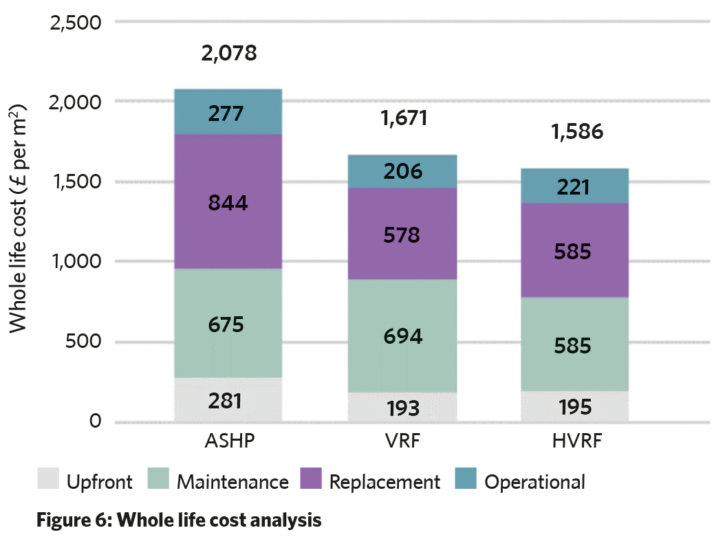
The whole life cost for each system over a 60-year period has been analysed by using a cost (£ per m2 ) value obtained from similar buildings, and is presented in Figure 6. This shows that the upfront capital cost to install an ASHP system is more expensive than the VRF or HVRF, which are comparable.
This remains the case when maintenance, replacement and operational costs are considered, with the HVRF being slightly cheaper than the VRF system. Note, HFCs such as R410a are expected to become more expensive, which will increase maintenance costs.
Historically, water-based systems enable closer control of off-coil temperatures compared with refrigerant ones, allowing for greater control over room temperatures and thermal comfort. Recent advances have reduced this disparity, however. The closer control is due to water being a more stable heat-transfer medium than refrigerant, giving the ASHP four-pipe FCU systems an advantage over VRF when we consider occupant comfort.
HVRF aims to solve this problem by providing the function of a four-pipe fan coil system and the efficiency of modern VRF in one system, by switching to a water-based distribution system on office floors, which results in high sensible cooling and efficient heating. Load-capacity control is achieved through inverter-driven pumps and flow control valves, which can be built into the hybrid branch controller.
Key conclusions
The global warming impact of refrigerant fugitive emissions can represent a significant proportion of a development’s WLC emissions. A standard VRF installation, employing R410a refrigerant, can generate more than twice the emissions of a gas boiler system over a 60-year period. To reduce emissions, industry must focus on minimising the volume of refrigerants, specifying refrigerant with a low GWP; and reducing leakage rate through inspections and maintenance.
The ASHP has the lowest WLC emissions of the three systems, despite performing slightly worse operationally. Plant space, whole life cost and thermal comfort are also important factors when considering system selection.
About the authors
Main author Will Belfield, Graduate CIBSE Member, is a sustainability consultant at Hoare Lea
Supporting author Mathew Stark, Graduate CIBSE Member, is a mechanical engineer at Hoare Lea