Low-voltage electrical distribution software design packages have been of great value to those involved in the design of low-voltage electrical distribution networks. The software’s calculations streamline electrical design production, and complex low-voltage distribution systems can be modelled quickly. However, caution should be exercised when working with the input data and output calculation results.
There are various low-voltage electrical design software packages on the market, which typically provide a platform for the designer to model low-voltage electrical distribution networks. These networks may comprise electrical transformers, generators, switchboards, distribution boards, electrical loads, cabling, and protective devices.
Based on the input design data, the software will carry out the required calculations. For UK installations, the low-voltage electrical designs and associated calculations should be in accordance with BS 7671 Requirements for electrical installations and any specific client requirements.
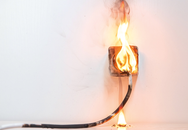
A minor change between the designed circuit parameters and installed circuit could lead to the risk of fire
Calculation result analysis
The examples below show the output from commercial software. These are free from any errors, but there are still small margins between the calculated results and the required limiting values.
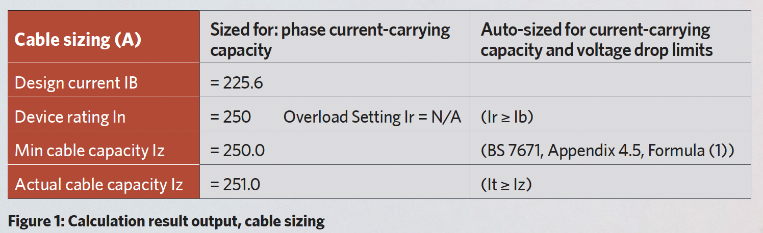
Calculation #1 – cable current-carrying capacity
Calculations have determined that the circuit requires a cable with a minimum current-carrying capacity (Iz) of 250 amperes (A). The designer may select – or, in some instances, the software may automatically select – a cable with a tabulated current-carrying capacity (It) of 251A, leaving a very small margin of 1A between the cable’s minimum current-carrying capacity and its actual tabulated current-carrying capacity. The software or designer may allow this small margin, as it satisfies the requirements of BS 7671.
A minor change to the cable installation conditions on site could adversely affect the rating factors used at the design stage to calculate the cable’s minimum current-carrying capacity. This could lead to the installed cable operating at a current that exceeds its tabulated current-carrying capacity, which would result in the cable overheating and its insulation degrading or, at worst, melting – creating the potential risk of fire and/or electric shock.
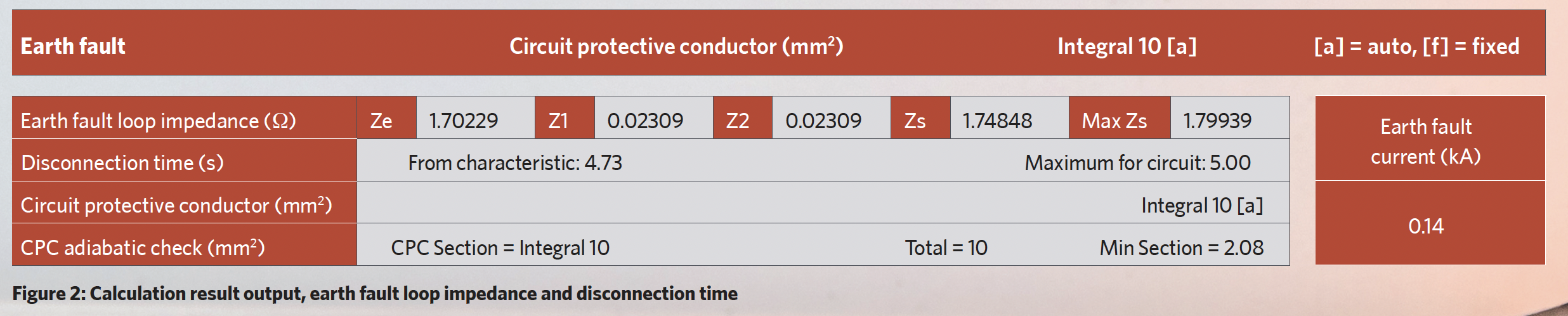
Calculation #2 – earth fault loop impedance and disconnection time
Calculations have determined that the circuit’s earth fault loop impedance (Zs) is 1.74848 ohms, and the circuit’s limiting maximum Zs value is 1.79939 ohms. (The earth fault loop impedance values are to five decimal places, as taken from the software calculation result output in Figure 2 below, but two decimal places should be sufficient). The circuit has a corresponding disconnection time of 4.73 seconds, with the maximum disconnection time for this particular circuit being 5 seconds.
The calculated earth fault loop impedance is around 97.2% of the maximum allowable earth fault loop impedance, leaving a small margin of only 2.8% between the calculated and maximum Zs values. There is also a small margin of approximately 0.27 seconds between the actual disconnection time and the maximum circuit disconnection time.
The software or designer may allow these small margins as the calculated earth fault loop impedance is less than the maximum Zs value, and the actual disconnection time is less than the maximum for the circuit.
It is important to note that, if the circuit cabling is installed on site, with an increased length of run, there is a potential that the earth fault loop impedance will increase, which may result in the circuit not disconnecting from the electrical supply within the required time. Again, this could lead to the installed cable operating at a current that exceeds its tabulated current-carrying capacity, causing overheating.
As seen in the above examples, calculation results that have no errors can still pose a risk, allowing a low margin for error between the designed circuit and the installed circuit. In an ideal world, the physical installation would align with the design input data – but this is not always achieved.
The calculation reports must be thoroughly checked, taking cognisance of small margins between the calculated values and the required limiting values. The designer should determine what margins they consider to be appropriate to minimise any potential risks, and this information should be clearly identified and recorded.
To verify the accuracy of the calculation output results from the software, a number of hand calculations could be carried out and the results reviewed against the corresponding software results.
The risks identified in the calculation result analysis examples above are expanded upon in the panel.
Potential risks
Equipment damage: Overheating of a cable can lead to damage to its insulating materials, potentially leading to a shortened useful life expectancy because of premature failure. Overheating is not restricted to the cable itself; it can also manifest and cause damage to the associated cable terminations at protective devices, socket outlets, light fittings, and other connected equipment.
Fire: According to the Home Office’s detailed analysis1 of fires attended by the Fire and Rescue Services, there were 63,482 primary fires recorded in England between 2021 and 2022, and 6,762 of those fires had their source of ignition identified as ‘electrical distribution’.
Electrical distribution as a source of ignition accounts for 12.4% of the causes of primary fires in dwellings and for 15.7% of the causes of primary fires in other buildings.
Note that electrical distribution could comprise the incoming electrical supply, electrical distribution boards, cabling, socket outlets, and such.
Electric shock: Cable insulation that has degraded or melted could expose live cable cores, introducing a potential electric shock risk from either direct contact with the live cores or indirect contact with exposed conductive parts that have become live under fault conditions.
Summary
Low-voltage electrical distribution design software packages are great tools, performing multiple complex calculations in seconds and streamlining design production. But, like any tool, it should be used intelligently. The calculation results should not be accepted at face value, as there is a potential for small margins between calculated and limiting values to be present.
A minor change between the designed circuit parameters and the installed circuit could lead to component degradation or the risk of fire.
The responsibility lies with the designer to check both the input data and the output calculation results, including the calculation results that have passed with no errors.
Another problem of software always reducing cable sizes to their minimum is that if, during a later design change, the final circuit loads increase, this can have a cascade effect on the whole of that distribution circuit (or others), where, suddenly, all the cables have increased by one size.
It is favourable that some key design information should go forward with the final design. It would be impractical (and undesirable) to provide all the data for every cable, but, certainly, for the main distribution circuits, it would be worth recording on the design drawings, distribution board schedules, and so on the factors that ‘decided’ the final choice of cable size. For example: tabulated current value; required or limiting current value; grouping factor and ambient temperature factor.
If any load increases occur during construction (or after/during operation), engineers can then decide if that additional load can be safely carried by the circuit (with perhaps a slight increase in voltage loss), or whether a new or second distribution cable needs to be installed.
Thorough checking of the input and output data, and the recording of key design information, will reduce design errors and minimise potential risks.
About the author:
Simon Rae is associate director of Diales Technical
References:
- Home Office Fire Statistics Table ‘0602a: Primary fires by source of ignition and whether the cause was by human/non-human factors, England’