![]()
Steel has been made for several thousand years, originally by the fortuitous introduction of carbon to molten iron and, in modern times, by employing carefully controlled processes to produce precise qualities of steel. Iron is commonly found around the world as ore, a stone comprising iron oxide and a mixture of other minerals known as ‘gangue minerals’.
Crushed ore is heated in a blast furnace together with carbon, commonly in the form of coke, and other minerals, such as limestone, which acts as a flux in the removal of the gangue materials to create slag by-product. Preheated air, and gas or oil, is blasted from the base of the furnace, so that the temperature is as high as 1,700°C, and the carbon – being more reactive with oxygen than iron – displaces the iron from the iron oxide through a reduction reaction.
The resulting molten ‘pig iron’ that is taken directly from the base of the furnace can be used as ‘cast’ iron. However, as it contains around 2% to 4% of carbon, it is not only very hard, but very brittle and not weldable. (If less than about 0.1% of the carbon remained, the resulting metal might be considered as wrought iron, which is quite soft and easily worked, but has little structural strength.)
To transform the pig iron into usable steel, the impurities in the iron – including some of the carbon, sulphur, phosphorus and silicon – are selectively removed by employing several well-established minerals and processes. In particular, oxygen is blasted through the molten iron, which reacts with the remaining impurities to form various oxides, including carbon monoxide gas.
Higher amounts of residual carbon increase hardness and tensile strength, as well as improving the response to heat treatment (hardenability), but with reduced weldability. The resulting alloy of iron and carbon – known variously as ‘carbon’, ‘plain carbon’ and ‘ordinary’ steel – is likely to contain small residual amounts of additives such as silicon, aluminium and manganese that have been used to assist in the deoxidisation, plus cerium, which is added to control sulphur in the steel that otherwise can make it brittle.
Carefully regulated regimes of heating and cooling are employed to produce the required crystalline structure of the resulting steel.
Carbon steels are typically classified, based on their carbon content, as low, medium and high. Low-carbon steel, which is also known as mild steel, has typically 0.05% to 0.25% carbon and is malleable and ductile, but has a relatively low tensile strength; medium-carbon steel has 0.25% to 0.6% carbon; and high-carbon steel ranges from around 0.6% to 1.5% carbon, which is very hard and increasingly brittle as the carbon content increases.
To enhance specific properties, alloying elements other than carbon may be added to create what are known as ‘alloy steels’, such as stainless steel. Molten mild steel can be made into slabs for later processing, or produced in a continuous process, employing hot rolling techniques, to form sheets, bars and coils of steel. Mild steel is typically employed for pipe fabrication.
There are two main methods to create steel pipes from mild steel – seamless and welded. Seamless pipe is formed by two principal techniques: hot rolling for larger pipes and cold drawing for smaller pipes. The hot rolling method forces a solid billet (a precise length of steel bar) that has been heated to approximately 1,250°C over a ‘piercing rod’ to create the hollow shell.
The hot, hollowed billet is then passed through successive sets of concave rollers that form a pipe of the appropriate external diameter and pipe wall thickness. It is then cleaned and cooled.
Cold drawing takes a previously produced large diameter tube ‘blank’ and then, following a series of intermediate treatments, draws (or stretches) the pipe into a precisely dimensioned, smaller diameter pipe.
Welded pipe is typically formed from a continuous feed of sheet steel (from rolls of mild steel that are butt-welded together as they are unrolled), passing between pairs of increasingly convex/concave rollers, and the resulting U-shaped steel channel then passing between pairs of progressively concave rollers to form a pipe. The seam is electrically welded and the weld cleaned and smoothed.
Having created the pipe with appropriate dimensions, after straightening (through rollers) and some quality assurance checks, it is sometimes lacquered/painted, and then marked to indicate the specification of pipe. The characteristic ‘black’ finish on unpainted mild steel pipe is iron oxide that naturally occurs in air.
Seamless pipes are perceived to be stronger and more reliable. However, modern processes and quality assurance tests have minimised the difference in robustness. Welded pipe is smoother, more uniform and cheaper to manufacture than seamless pipe, so is commonly used in building services applications for non-potable water such as low-pressure water, heating, cooling, and gas.
The inherent strength of welded pipe is formally taken as being around 20% less than the equivalent seamless pipe (as required by standards).
The ‘nominal’ pipe bore (the diameter of the hollow core) is the approximate internal measurement. External diameters are standardised internationally – identified in terms of the nominal bore – to allow universal fitting. Metric sizes of steel pipework are specified by ‘diamètre nominal’ (DN), which is dimensionless but indirectly related to the physical size, in millimetres, and imperial sizes by ‘nominal bore’ (NB), in inches. Owing to different weights (wall thicknesses) – also known as ‘schedules’ – of steel pipe, the true bore size of pipes will vary.
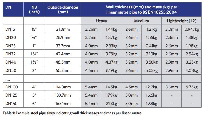
In the UK and Europe, mild steel pipe that is suitable for heating, cooling and non-potable water services up to DN150 is standardised with BS EN 10255:2004.1 It is categorised as heavy (H), medium (M) or light (L), and made to the standardised external diameters, but with different wall thicknesses (and so strengths and resistance to corrosion), as shown in the examples in Table 1.
As noted by CIBSE Guide B1: ‘The main drawback of steel pipe is that it will corrode rapidly in the presence of water and oxygen. Hence, external surfaces should be painted with an anti-corrosion paint while internal surfaces should be protected by corrosion inhibitor chemicals.’ As part of the manufacturing process, suitably prepared pipe can be galvanised by being hot-dipped – submerged in a hot bath of molten zinc at around 500°C – to make the steel pipe more resistant to corrosion.
However, galvanised pipe has limited application in contemporary buildings – it is mainly restricted to legacy use in water systems for building fire protection.
There are several tried and tested methods for connecting mild steel pipe. The first two employ welding. The most popular method for welding pipe is the shielded metal-arc process, where a coalescence of metals is produced by heat from an electric arc maintained between the tip of a consumable electrode and the surface of the pipe or fitting.
Butt-welded joints are commonly used for DN50 and larger steel pipes – the welding process creates a weld bead, both internally and externally. These are often left in place, but can be removed using special tooling if necessary.
Socket-welded joints are formed by inserting socket connections onto the ends of each of the pipes to be joined, which are then welded in place. These joints are almost exclusively used in joining small-bore piping. An advantage with this type of joint is that the filler metal (from the weld) cannot enter the main pipe bore, so resulting in a smooth internal surface.
It is cheaper than the butt-weld (as it is easier to set up), but includes an expansion space between the end of the pipe and the fitting’s shoulder, which can cause corrosion problems. In general, welded pipe joints offer less resistance to flow than the mechanical connections (which are discussed on the next page).
A properly completed welded joint has a high temperature and pressure rating for the resulting ‘inseparable’ connection. The basic costs of materials and fittings are lower than many of the other connection methods, but welding can be a time-consuming method that requires skilled and properly protected pipe fitters.
It has been concluded2 that welding fumes cause cancer, and ultraviolet (UV) exposure from arc-welding processes causes melanoma in the eye and may increase the risk of skin cancer. As a result, there are recently revised Control of Substances Hazardous to Health (COSHH) Regulations requirements3 that relate to providing specific ventilation control and respiratory protective equipment (RPE).
Bolted flange joints are typically used for DN50 and larger mild steel pipes, and are common where pipe, piping components or equipment must be disassembled for maintenance. Flanges, to BS EN 1092-1:2018,4 can be added to the end of mild steel pipes by welding (typically using ‘slip-on’ flanges) or, in smaller sizes, by threaded flanges (which do not require any ‘hot work’ – use of naked flames – on site) that include a thread in the flange bore to connect to threaded pipe.
Flanged components are connected using bolts, and the flange pressure rating will increase with the number of bolts, the flange outer diameter and the flange thickness. Opposing flange faces are tightened against a rubber, fibre, composite or metal gasket.
The remaining connection methods do not require any ‘hot work’. Threaded or screwed joints are commonly used for smaller-sized steel pipes – typically DN50 or smaller. These are screwed together on site using fittings and pipes with threads to BS EN 10226-1:2004.5 Tapered pipe threads are cut by dies, frequently on site using a portable electric machine, and the resultant threads are rough and imperfect. A pipe jointing compound or thread sealant must therefore be used to prevent leakage from around the threads. This also acts as a lubricant when tightening the joint.
Grooved-end joints may be used for jointing steel pipes, and are readily removable for component maintenance and repair. Grooves are cold rolled or cut into the ends of the two pipes to be jointed, which are used in conjunction with proprietary fittings. The pipes are aligned, with a gasket bridging across the two joining ends A two-part coupling is fitted over the gasket to engage into the grooves. The two parts of the coupling are connected and tightened around the gasket by fixing bolts to create a secure, watertight seal.
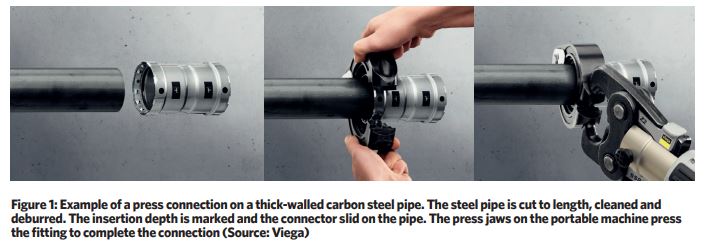
Cold press-connection technology has seen significant development in recent years, both in terms of components and, with the revolution in battery-powered equipment, in the method of application.
In recent years, systems have also become available for thick-walled heavy steel pipes that are able to work with both water and gas services employed in building systems. Using proprietary fittings, plain mild-steel pipes can be swiftly connected, as illustrated in Figure 1, using a portable, hand-held, battery powered pressing machine.
A standard sealing element – for example, EPDM – in a press-fitting would typically enable use in water systems between -25°C and +110°C with working pressures of up to 1.6MPa. Fittings are designed so that there is a clear leak path (and so quickly visible during system testing and proving) if they have not been pressed.
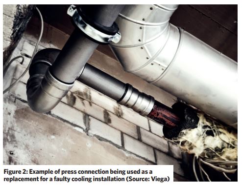
Press-fittings are available that can convert between legacy systems and new pipework that may be found in refurbishment works – for example, when replacing a boiler or simply when used to replace faulty components (as illustrated in Figure 2).
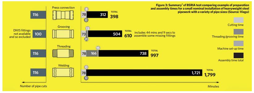
On behalf of a press-connection manufacturer, BSRIA conducted a study6 for a nominal small installation with a variety of 116 pipe connections of thick-walled steel tube, comparing the time required to prepare and complete the connections using welded, screwed, grooved and press methods. As illustrated in Figure 3, the study indicated significant differences in overall installation times.
Each of the outlined installation methods provides robust connections for mild-steel pipework and each has particular attributes. The choice of the method that is most appropriate for a specific application should be made by taking a holistic view of the advantages and disadvantages of each.
This will include health and safety (including restrictions on hot work); need for demountability; temperature and pressure requirements; material and equipment costs; skills needs of pipe fitters; access for fixing equipment; location and size of pipework; impact on operational costs (such as pressure drop and ongoing maintenance); and the total cost of installation. Pragmatically, real-world solutions may need to employ more than one method across a building services project.
© Tim Dwyer, 2022.
Further reading:
CIBSE Guide B1 Heating: 2016 provides an extended discussion on piping types and connection methods (including a useful appendix).
References:
1 BS EN 10255:2004
2 HSE Workplace Health Expert Committee (WHEC) Assessment of the strength of evidence underpinning the IARC reclassification of welding fume as carcinogenic to humans, WHEC-11a, 2019.
3 Welding, hot work and allied processes – WL3 – Welding fume control, HSE 2021.
4 BS EN 1092-1:2018 Flanges and their joints – circular flanges for pipes, valves, fittings and accessories, PN designated. Steel flanges, BSI 2019.
5 BS EN 10226-1:2004 – Pipe threads where pressure-tight joints are made on the threads. Taper external threads and parallel internal threads – dimensions, tolerances and designation, BSI 2010.
6 BSRIA report summary – Traditional pipework methods vs Viega Megapress, Viega –