![]()
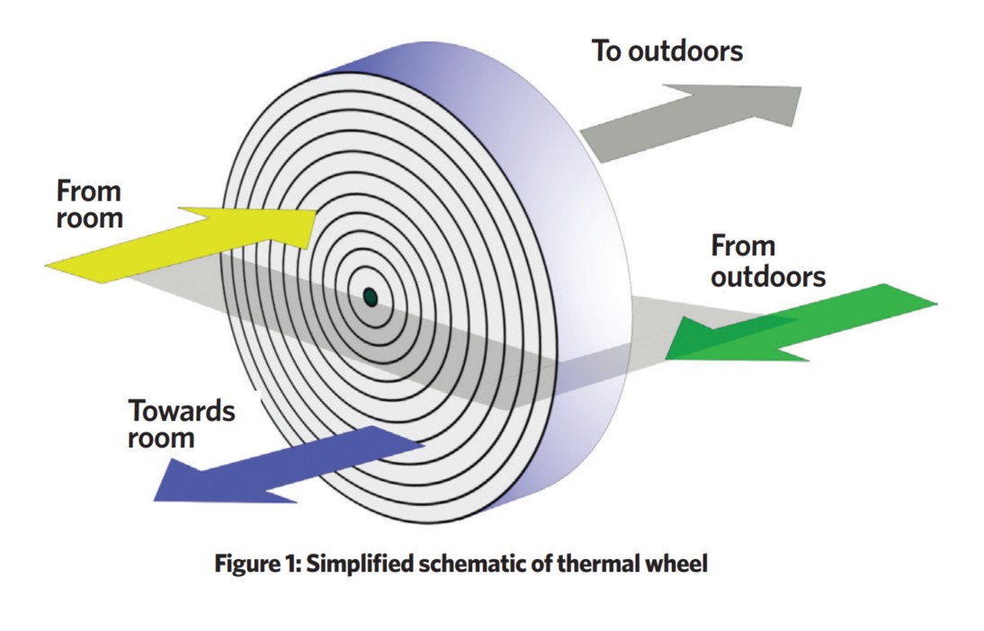
The thermal wheel – which, depending on its main function, may also be referred to as a heat wheel, rotary heat exchanger, and energy or enthalpy wheel – is based around a rotating cylinder that is packed with a material fabricated so that there are continuous channels passing from one side of the cylinder to the other, through which air passes. The packing material, which is typically aluminium, provides a large surface area to transfer heat between it and the passing airstream. The wheel is positioned in a casing, so that, at any one time, half of the wheel is exposed to an airstream – typically outdoor air – while the other divided half is in a counterflowing airstream that is being extracted, typically from the conditioned space.
The two halves are separated by a horizontal plate that has a critical, resilient seal against the wheel, which prevents leakage between the two air paths. Depending on the manufacturer, the seal is likely to be a brush-type contact seal that, although cheaper, can become more susceptible to leakage as the pressure differential increases; or a closely fitting, shaped, non-contact wiper seal that employs air vortices to maintain a seal. A simplified wheel – shown in Figure 1 – when operating for ‘winter’ operation, would take air extracted from a warm and humid room, its temperature and, potentially, the absolute humidity being reduced as it passes through the cool packing. Then, as the wheel rotates into the supply airstream, the heat is exchanged to the incoming cooler dryer outdoor air.
The wheel will typically rotate continuously, belt- or chain-driven by a low-power electric motor. The rotational speed can normally be modulated, or the wheel stopped, to suit the particular conditions.
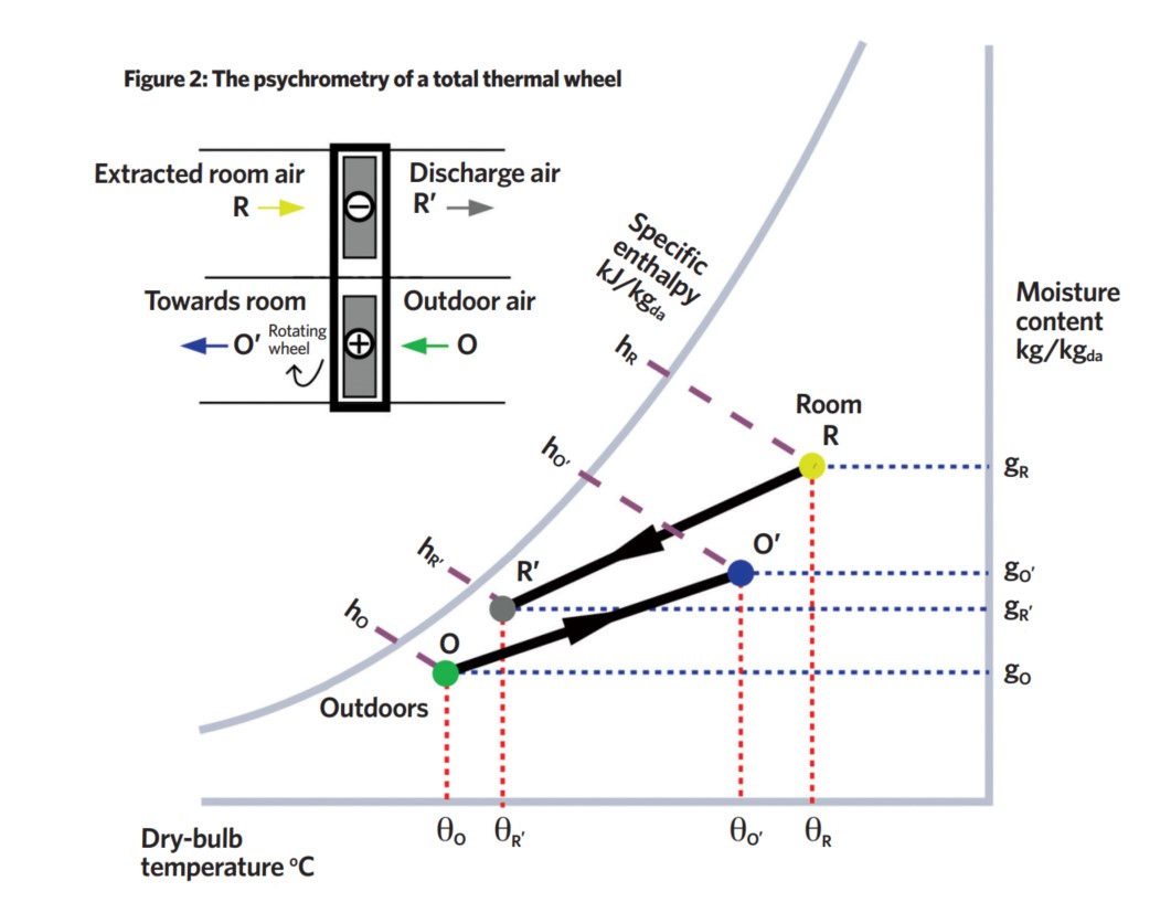
The heat that is transferred via the regenerative wheel between the two airstreams may just be sensible heat, leading to a change in the dry-bulb temperature in both streams. More effectively, when the packing has surfaces that are hygroscopic, or that have a sorption coating, this may also include latent heat transfer, so affecting both the dry-bulb temperature and the air moisture content, as shown in Figure 2. Even where there is no specific coating to promote latent heat transfer, condensation will occur when the temperature of the packing material falls below the dew-point temperature of the warmer airstream and releases a proportion of the latent heat of vaporisation to the packing.
Referring to Figure 2, the practical thermal effectiveness (ε) of the heat-recovery devices may be described in a number of ways.
In terms of sensible heat exchange εS = mO(θO’ – θO)/mR (θR – θO), and for latent heat exchange, εL = mO(gO’ – gO)/mR(gR – gO), where the values of εS and εL are not necessarily equal for a device that has both sensible and latent heat exchange. ( is mass flowrate of air). In terms of total heat exchange, the enthalpies of the airstreams may be used to give εT = mO(hO’ – hO)/mR (hR – hO). Modulation of output is commonly achieved either by adjusting the rotational speed of the wheel or by bypassing the supply air. Heat-recovery efficiency increases with wheel speed, but is ultimately limited by carryover (as discussed later).
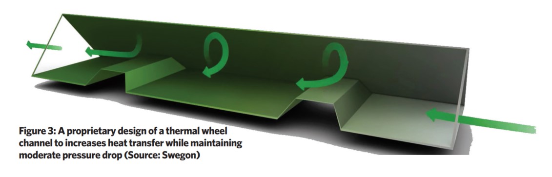
The heat-transfer properties are largely determined by the packing material that, in simple wheels, is often corrugated into sinusoidal-shaped channels. From tests of thermal wheels and validated models reported by De Antonellis et al,3 the most effective configurations are characterised by thin packing materials that provide a large accessible thermal mass across the face of the cylinder during the brief period as the cylinder rotates and air flows through the channels in each respective direction. The work also determined that a revolution speed – which is typically between 10 and 15 revolutions per minute – has little impact on the wheel effectiveness, but that, at higher speeds, there is an increased opportunity for the unwanted carryover of air between the two streams. If the heat wheel rotates slowly, the packing material average temperature becomes close to that of the airstream, so heat transfer decreases because of a reduced temperature difference. Deeper wheels benefit from larger channels. Some manufacturers employ more sophisticated metal channel profiles, such as that shown in Figure 3, to increase heat transfer while maintaining moderate airflow resistance.
The Ecodesign regulations1 require a thermal bypass for mechanical ventilation and heat-recovery units. When employing a thermal wheel, the thermal bypass is achieved by simply stopping the rotation of the wheel. Dependent on the application, a small ‘ducted’ bypass around the wheel can provide reductions in fan energy for when the wheel is stopped.
Cross-contamination of the two airstreams can occur by carryover and leakage. This can be minimised by: controlling the pressure differences between the two airstreams; providing effective seals; and configuring the respective fans in a way that always promotes leakage towards the exhaust airstream. Any leakage will incur a loss of effectiveness and an increase in fan power.
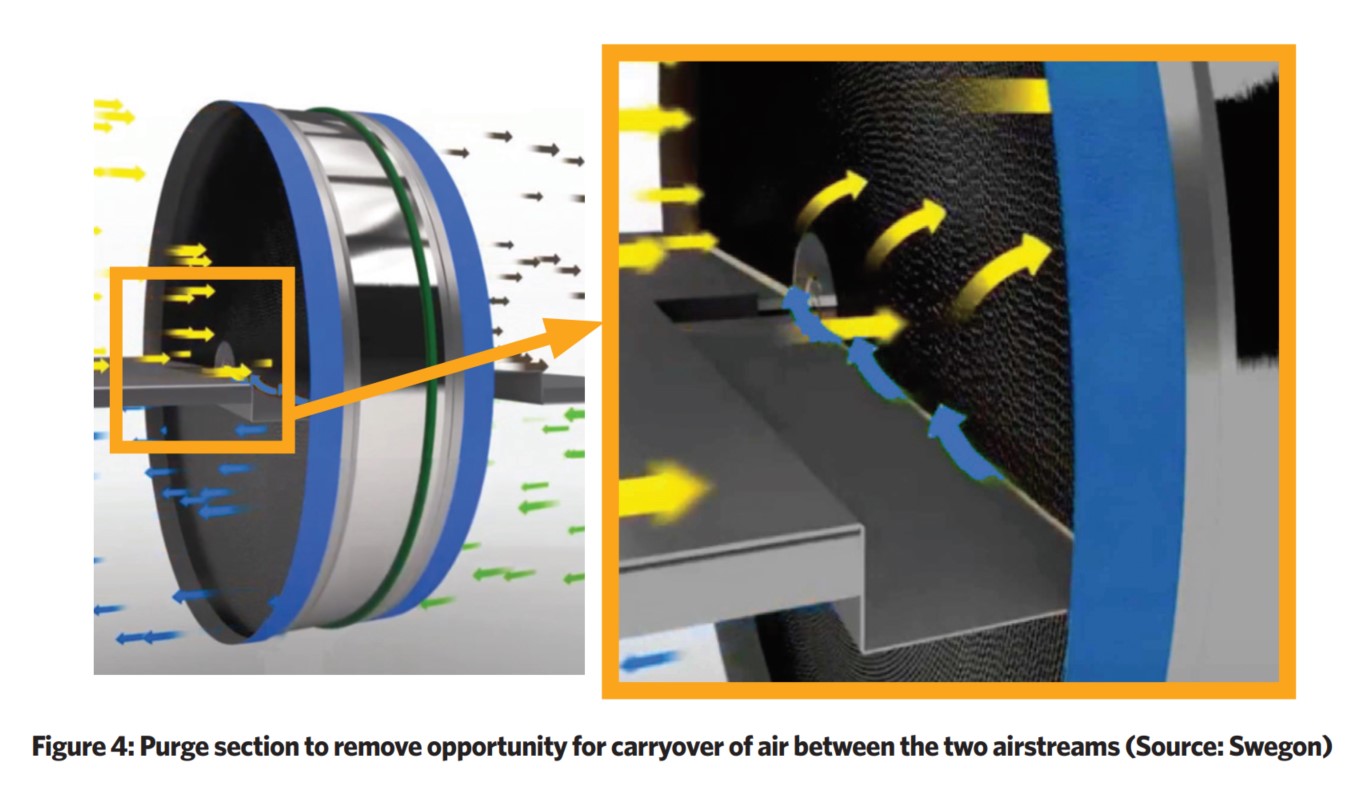
Carryover refers to the air that is entrained within the wheel, which is then transferred to the other, counterflowing airstream as the wheel rotates. A purge section is typically installed, as shown in Figure 4. Incoming fresh air (at the bottom right in the diagram) is used to ‘purge’ the air extracted from the room (shown in yellow) that has been entrained in the wheel, and then propels it into the exhaust airstream (top right). Increasing the purge rate reduces the capacity of the thermal wheel, as it will also transfer some of the heat into the discharge air. The extract fan drives this purging flow, so this will impact the extract fan operation and consumed power. An appropriately controlled wheel with a properly designed purging section can practically eliminate carryover.
Any leakage around the periphery of the wheel will impact the overall thermal performance and can contribute to the amount of air passing between the two airstreams, so it is important to employ good-quality, maintained seals. There should be a positive pressure difference between the incoming, outdoor air, side of the wheel and the exhaust side, so driving any leakage from the supply to exhaust. This prevents adversely impacting supply air quality but, as the pressure difference rises, will reduce the overall energy efficiency of the thermal wheel. The supply and extract systems should be commissioned to ensure that appropriate pressurisation is maintained. As the supply fan speed modulates (in response to demands from the room) the relative pressures must be automatically monitored and extract fan speed varied appropriately. There may be a need for an automatically controlled damper in the return ductwork to maintain a correct pressure differential, and any additional pressure drop for the damper must be catered for by the exhaust fan. As airflows modulate, the rotary heat exchanger speed should be controlled automatically to ensure appropriate purging.
Abstracted notes from CIBSE Covid-19 ventilation guidance, version 4, 23 October 2020
Where thermal (or enthalpy) wheels are installed to recover heat, then a competent engineer/technician should check that the configuration and operating conditions are such that any leakage across the device is from the supply side to the extract side, to minimise the risk of transferring contaminated air into the supply. However, if adequate ventilation rates with suitable thermal comfort can be provided without use of the regenerative rotary heat exchanger, then it is advisable to bypass the system if provision is available – or, if no bypass is available, then the rotor should be turned off.
The heat-recovery function is usually integral to the system design in terms of simultaneously delivering adequate airflow and meeting heating or cooling demand. If the only way to provide adequate and safe outside airflows is by using the thermal wheel, then it is advisable to turn the rotor on. ….. The expected reduction in dilution of any potential indoor viral source with inadequate ventilation flowrates is considered to be a greater risk for viral transmission than the potential for viral transfer across the thermal wheel. Turning the rotor on will also improve thermal comfort conditions, and has the added benefits of maintaining the energy efficiency of the system and helping to maintain appropriate humidity levels in the building.
(See the full document here).
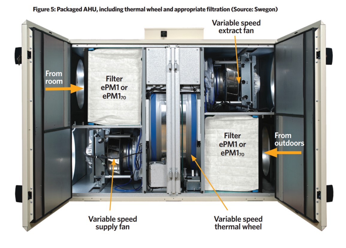
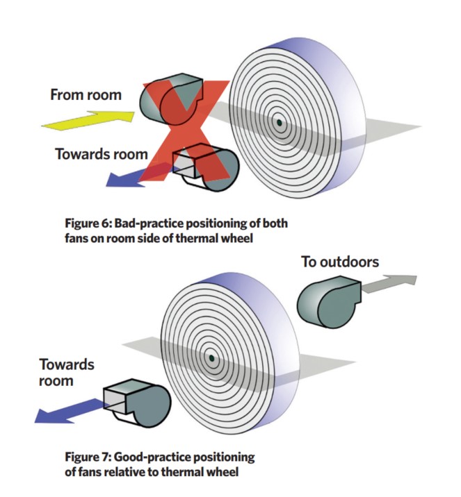
If the AHU is configured incorrectly, as in Figure 6 – with both the extract and the supply fan placed on the room side of the wheel – then leakage is likely to have a serious effect on the air quality, as this arrangement will subject the seals to the maximum possible pressure differential. To minimise the leakage of air between the airflows, a recommended arrangement of the fans is downstream of the wheel on both sides, as shown in Figure 5 and Figure 7.
BS EN 16798-3:20174 employs two ratios to assist in the characterisation of leakage. Outdoor air correction factor (OACF) is the ratio of the air mass flowrate of outdoor air entering the heat-recovery device to the mass flowrate leaving the device towards the room. An OACF of less than 1 indicates leakage from exhaust to supply. Exhaust air transfer ratio (EATR) is the percentage of exhaust air passing to the supply air through the seal around the wheel, together with any carryover leakage. It is reported that a soon-to-be-published Eurovent REC 6/15-2020 guideline will effectively limit EATR to 1% and OACF to between 0.9 and 1.1.5 However, as OACF increases above 1, the fan energy use can increase significantly. The values of EATR and OACF will also be dependent on the pressure drop in the distribution ductwork. For a more detailed explanation of the EATR and OACF see Eurovent 17/11:2015 – Guidelines for Heat Recovery.
Wheels – particularly hygroscopic wheels – can carry water-soluble gases (such as cooking odours and tobacco smoke) between the two airstreams. In many applications, this is unlikely to be a problem, but will be a consideration when selecting a heat exchanger for areas such as restaurants. If the discharge airstream is contaminated with dust, bacteria or viruses, there could be carryover from one stream to another. However, where the unit is operated appropriately, this is thought to be a very small percentage, and with correctly maintained ePM1 or ePM170 filtration upstream of the wheel – such as that shown in the unit in Figure 5 – this should not be a practical problem. As the world looks forward to emerging from the Covid-19 pandemic, the impact of ventilation systems on indoor air quality has never been more important. CIBSE’s current guidance on ventilation systems related to Covid-19 (abstracted in boxout) concludes that ‘the benefits of maintaining high outside air rates to dilute internal viral contaminants outweigh the risks of viral particles being transferred via a correctly configured thermal wheel’.
© Tim Dwyer, 2020.
References:
- The Ecodesign for Energy-related Products Regulations 2010.
- Energy Technology List, accessed 6 November 2020.
- De Antonellis, S et al, Design optimization of heat wheels for energy recovery in HVAC systems, Energies 2014, 7, 7348-7367; doi:10.3390/en7117348.
- Energy performance of buildings – Ventilation for buildings – Part 3: For non-residential buildings – Performance requirements for ventilation and room-conditioning systems.
- Lawrance, W and Schreck, T, Rotary heat exchangers save energy and prevent a need for recirculation which contributes to the decrease the risk of Covid-19 transfer, REHVA Journal, Vol 57, Issue 5, October 2020.