![]()
This CPD will consider what causes backflow and the circumstances where non-mechanical means may be used to prevent such backflow.
For backflow to occur, there needs be a cross-connection and a pressure difference between wholesome water (formerly typically known as ‘potable water’), and potentially contaminated water. This connection may be direct or indirect.
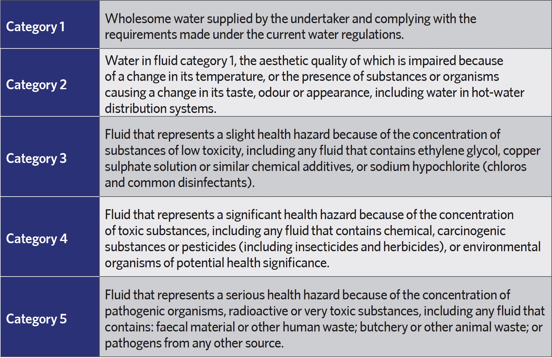
Table 1: Categories applied to assess backflow risk
Direct connections are where a pipe (or device) is connected directly to another pipe, or a ‘receptacle’ – for example, a cistern, vessel, fitting or appliance5 – and so provides a clear route for potential contamination. A commonly seen example is where flexible filling loops, used to fill heating systems, are inadvertently left connected to the main service water pipe after completion of commissioning.
Indirect, or submerged, connections are where the supply point – such as tap or hose outlet – is inappropriately immersed in water. A hose outlet that is left to rest submerged in water is a common case – as might be seen, for example, in a sink or bucket in a wash-up area; a flexible shower head in a bath or toilet; or a garden hose in a filled bucket, drain or paddling pool. In the recent flooding in the UK, there were many wholesome water outlets that, although not normally a backflow risk, would have become submerged, providing opportunity for backflow that added to the miseries of the unfortunate building occupiers and water service providers.
Providing there is a cross-connection, water will flow from a point of high pressure to that of lower pressure. In normal operation, the water outlet, or supply point, would be at a higher pressure than the point of delivery. For a tap outlet, the point of delivery would typically be at atmospheric pressure. In the UK, the statutory1 service standard of mains water pressure to consumers is 0.7bar (70kPa), although it is commonly higher than this. So, any inadvertent cross-connection from a consumer-side water service that is operating at a pressure higher than 0.7bar could cause backflow. This equates to a water head of about 7m – so if, say, the consumer system included a connected water tank (cistern) higher than 7m above the water-service pipe (or the consumer’s system was pressurised above 0.7bar), there would be opportunity for backflow to the mains supply because of the back pressure.
The mains water pressure may drop significantly below 0.7bar if there is a break in the water main, a failure in pumping, or an unusually large demand on the system – for example, when a fire hydrant or an inappropriately connected irrigation system is in use. As the pressure in the mains supply drops below that of the consumer system, the opportunity for back siphonage of water from the consumer side into the mains water service will increase. After a break to the mains supply, or maintenance, the water supply authority would ensure that the restored water supply is wholesome. However, where the pressure reduction in the mains supply is caused by transient excessive demand, this can potentially cause undetected backflow and so contaminate the water supply. Recorded incidents of backflow2, 3 indicate that it occurs mainly as a result of cross-connections that contravene the water byelaws or have been inappropriately operated/installed. However, hoses that are left with the outlet submerged, and ‘temporary’ connections that are inappropriately left in place, were also identified as causes of backflow due to back siphonage. To reduce the risks from hoses, it has been illegal since 1999 for commercial organisations to connect a hosepipe directly to a tap to wash down machinery or a vehicle – this requires appropriate backflow protection.
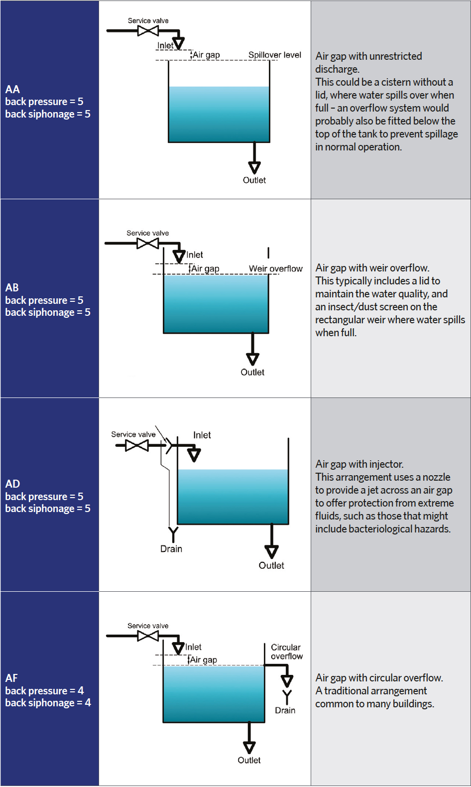
Table 2: Schematics of common non-mechanical backflow arrangements. Real applications would include a control mechanism to meter the incoming water, vents, overflow arrangements and insulation, and (possibly aside from AA) would typically include a lid
Pressure fluctuations and backflow may occur within the confines of the pipework in a building that – particularly where the piping layout is not properly installed, or where there is a fault – can cause contamination of the supply to outlets within that building. A particularly obvious manifestation is where taps have been seen to pass blue water – caused by a malfunctioning toilet-cistern float valve on an upper floor – that, when the pressure drops in the pipework system, ‘back siphons’ water, stained blue with a toilet disinfectant block, from the cistern into the supply pipework.
Preventing backflow
There are a number of publications that provide guidance on the recommendations and standards to avoid backflow, including the specific backflow prevention standard BS EN 1717:20004; and the local/regional water regulations such as, in the UK, the Water Supply Regulations, 19995 and Part G6 of the Building Regulations. The Water Regulations Advisory Scheme (WRAS – see www.wras.co.uk) produces excellent documentation that incorporates current guidance and the relevant UK information from the other publications – the Water Regulations Guide7 being one of its most comprehensive, as well as being superbly illustrated.
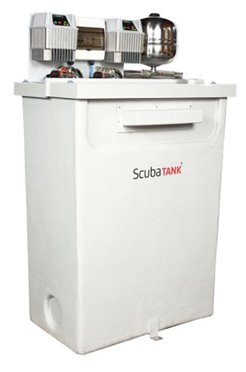
Figure 2: Example of a break tank with an AB air gap that can be used, for example, for refurbishment applications, as the smaller sizes in the range are made so that they fit through doors. The submerged pumps are almost silent in use; the integrated inverter control and pressure vessel is on top (Source: Dutypoint)
These documents provide details of the type of protection method – if any – required to prevent backflow contamination of wholesome water related to the potential hazard to human health, broken into five categories of flowing liquids. The higher the potential danger, the higher the category number. The need for protection, or type of protection device required, is determined by the liquid’s category number, as shown in Table 1. Category 1 represents drinking-quality water, while fluid category 5 is the most contaminated. The categories take account of the context of the particular application. So, for example, in private domestic dwellings, dishwashers and washing machines are rated as fluid category 3, but in commercial premises, the higher backflow risk is rated as fluid category 4 – and, if healthcare is provided in the premises, as fluid category 5. The backflow prevention specification then equates each fluid category to a range of suitable backflow-prevention methods for both back pressure and back siphonage. However, it is noted that in cases where insignificant concentrations, or substantial amounts, of substances are present in the fluids, it may be appropriate to redefine the backflow safety regime.
The arrangement that is deemed most appropriate in meeting standards will depend on the application and the requirements of the local regulations. Where an appliance is used, care needs to be taken to identify the backflow-protection requirements, and to ensure that the appliance has the appropriate protection incorporated within the machine, or has appropriate backflow protection installed upstream of the appliance. (Particular care should be exercised when using an appliance marketed as a domestic appliance in a more demanding commercial application.) Prevention measures include mechanical devices that are typically inline valve arrangements designed to prevent flow reversal and ensure that there are no sub-atmospheric pressures (‘anti-vacuum’) in the supply pipes. (These are not being discussed in this article – see WRAS Water Regulations Guide.7)
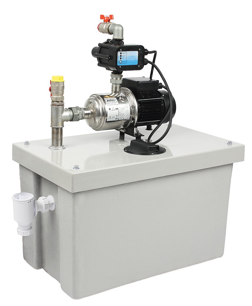
Figure 3: An example of a break tank and end suction booster pump set, featuring an electronic pressure controller and a type AB air gap that meet the requirements to prevent a category 5 backflow (Source: Dutypoint)
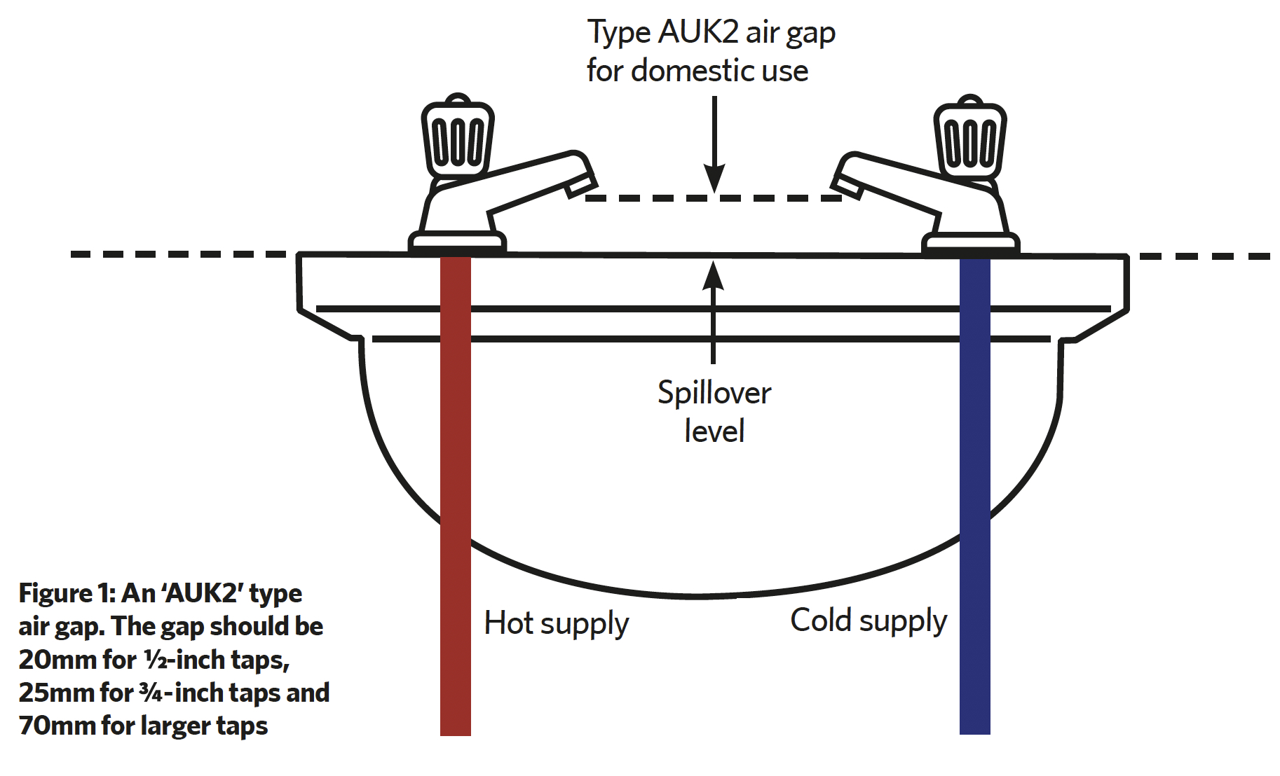
The most fundamental mechanism to prevent backflow is the ‘air gap’, known as a ‘non-mechanical backflow prevention arrangement’. An air gap provides a physical separation between the supply end of a water-supply pipe and the receiving receptacle, and, if properly installed and maintained, is effective at preventing backflow. The air gap is measured vertically (to within 15°) from the lowest end of the supply outlet to the spillover level (see Figure 1) or highest possible water level of the receptacle into which it discharges. The separation provided by the air gap must be twice the supply-pipe inside diameter, and never less than 20mm. Although this non-mechanical arrangement provides a robust defence, it can be compromised – for example, with funnels or hoses – and the incoming water may be exposed to airborne contaminants. The air gap is shown, in its most common application, in Figure 1. This particular air gap is designated as ‘AUK2’ – ‘A’ for air and ‘UK2’ for the specific sub-type. This is suitable for protection against category 3 fluid back siphonage, and is not applicable to back pressure.
AUK3 is similar, but relates to higher-risk taps (such as in laboratories) for back siphonage = 5. AUK1 is the arrangement to provide an appropriate gap when a toilet cistern is used in series with a storage tank (back pressure = 3, back siphonage = 5). There are six other air-gap designations, AA to AG. Those illustrated in Table 2 are probably the most common types used in UK building applications.
As any break-tank arrangements will lose any benefit from the mains supply water pressure for subsequent distribution (as the water will be at atmospheric pressure) systems are available to provide both backflow protection and pressurisation. So, for example, the 575-litre cistern in Figure 2 meets the requirements of the water supply regulations by incorporating an ‘AB’ air gap, and could be applied to serve commercial facilities to supply wash-down hoses. For simpler pressurisation applications – with no need for extensive storage and modulated flow – lower-cost systems, such as the 100-litre break tank and end suction booster pump illustrated in Figure 3, may be more appropriate, still maintaining an AB air gap.
© Tim Dwyer, 2020.
References:
- The guaranteed standards scheme (GSS): summary of standards and conditions, OfWat 2017.
- Curtis, C, Cross-connections and backflow prevention manual, West Virginia Bureau for Public Health Office of Environmental Health Services , 2011.
- A study of backflow events in England, Wales and Scotland, UK Department of the Environment, 1993.
- BS EN 1717:2000 Protection against pollution of potable water in water installations and general requirements of devices to prevent pollution by backflow.
- The Water Supply (Water Fittings) Regulations 1999.
- Approved Document G – Sanitation, hot water safety and water efficiency (2015 edition, with 2016 amendments).
- Water Regulations Guide, 2nd Edition, WRAS, 2000.