
This article will consider factors that will impact the success of an assessment of the building circulation loop for in-home water-to-water heat pumps designed to exchange heat with ‘ambient’ (otherwise known as ‘ultra-low temperature’) communal heat networks. Such a communal heat network is defined by CIBSE CP1 Heat networks: Code of Practice for the UK as one ‘that serves a single building that contains more than one customer (the building does not need to contain the plant)’.1
The January 2021 CIBSE Journal CPD, Module 174, explored the application of residential (‘in-home’2) water source heat pumps in conjunction with communal ambient heat networks, which maintain the temperature of an ambient loop – typically between 15°C and 25°C. This compares with a traditional building heat network circulating water in the order of 80°C to 70°C flow, with an expected 20K or 30K temperature drop through the load in each apartment. In-home heat pumps usually have a modest capacity of 4kW to 9kW and are therefore paired with a domestic hot water (DHW) storage system. As noted in the recently published CIBSE AM16 Heat pump installations for multi-unit residential buildings, the temperature of the ambient loop is maintained through landlord-operated plant, such as centralised heat pumps, gas boilers or connection to a wider district heating network, or potentially a passive ground loop array. As noted in CIBSE AM16, the cost to the landlord of operating the ambient loop and building-level plant may be passed to the residents through a service charge. As the heat pumps are powered from the residents’ electrical supply, most in-home heat pump systems can facilitate simplified billing and reduced standing charges.
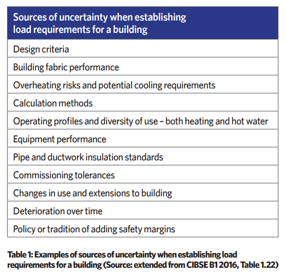
Ensuring that the ambient loop is sized appropriately to supply sufficient water at an appropriate flow temperature is dependent on the designer understanding the coincident load profile of the multiple demands across the building – which is not an exact science. Despite the increasing rigour in regulatory requirements for buildings and systems, there remain plenty of opportunities for uncertainty in the design process, which can result in systems that operate inefficiently, ineffectively, or both. Table 1 provides some examples of common areas that are likely to contribute to these uncertainties. The increased use of modelling and simulation, when employed appropriately, can undoubtedly improve the prediction of building and system performance, but that is predicated on a proper representation of the built environment being created in the virtual world. As somewhat controversially illustrated3 by Iman et al, the reliability of the modelled solution will also be dependent on the knowledge and skill of the modeller.
The peak heating, cooling and hot-water demand for a development may be obtained by calculation and modelling, or by monitoring demands of existing buildings. Actual data derived from similar operational buildings are extremely useful as a check on proposed designs.
As discussed in CP1,1 when employing communal networks for multi-residential systems, the peak heating demand for the building is always found to be significantly less than the sum of the peak design demands calculated for the individual dwellings. For example, many dwelling space heating demand calculations assume that there is heat loss to adjacent unoccupied properties. If these heat demands are then multiplied by the number of dwellings to give a block heat demand, there will be significant oversizing. A space heating diversity factor may be applied to the individual dwelling space heating demands, calculated to include heat losses to adjacent properties. CP11 recommends the ‘rule of thumb’ empirical formula from the Danish guidebook Varme Ståbi,4 illustrated in Figure 1.
For a small number of apartments, it would not be appropriate to apply the diversity factor but, as can be seen, groups of more than 10 apartments are likely to have a coincident heating demand of less than two-thirds the sum of individual peak demands.
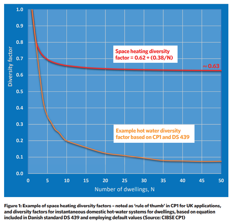
CIBSE AM16 highlights that accurate calculation of DHW loads is particularly important for the design of heat pump systems in multi-residential buildings, as DHW forms a large proportion of the overall heating load, in terms of both peak load and annual energy consumption. The flow temperature in the network is set to meet the specific needs of the residential systems, and this is often determined by the temperature required to meet domestic DHW needs. (The actual maximum temperature required for the DHW in the dwelling will depend on whether instantaneous or storage hot water is used – see the recent CIBSE note, Domestic hot water temperatures from instantaneous heat interface units, for a clear explanation of current thinking.) Realistic assessment of diversity (of use) is particularly important. There are continuing efforts to produce metrics that can be applied by the designer, including the CIBSE-supported Loading Unit Normalisation Assessment (LUNA) project,5 as it is thought that current practice tends to overestimate demand1. CIBSE CP11 recommends that the method of Danish standard DS 4396 may be applied, which employs a (relatively simple) equation that is clearly explained in CP1 – with an excellent example – and produces a demand in terms of a nominal cumulative design DHW flow. This was applied to provide the example diversity graph in Figure 1.
The resulting peak load on the heat network effectively relates to the demand from instantaneous hot-water heating – for example, as would be realised by employing heat interface units (HIUs) with a higher-temperature network. When applying ambient loops in conjunction with in-home heat pumps, it is highly likely that there will be some form of DHW storage, such as individual hot-water cylinders in each apartment. This can significantly reduce the peak load on the heat network, as heating of the water store may be scheduled to minimise the coincidence of multiple residences drawing heat at the same time. (Maximising this benefit requires considered design, building-wide control, and the compliance of the residents.)
The building network distribution losses will be dependent on the location and temperature of the pipework, and the insulation. So, for example, when considering heating systems, a communal network that passes through a heated space, such as a corridor or an equipment room, will have a lower temperature difference between the pipe and its surroundings, and so a lower potential heat loss than a pipe passing through an unheated area, such as an undercroft or a ventilated riser.
The thickness and efficacy of the insulation will be determined by a combination of considerations – including legislative, economic and space – as well as being dependent on the quality of installation. Practically, some losses will always occur, and these have been an inevitable part of the design and the operational efficiency of traditional systems. The overall efficiency of an already installed system will reduce as the thermal performance of building fabric and hot-water systems is increased, as the losses from the distribution network become a greater proportion of the total energy supplied to the building.
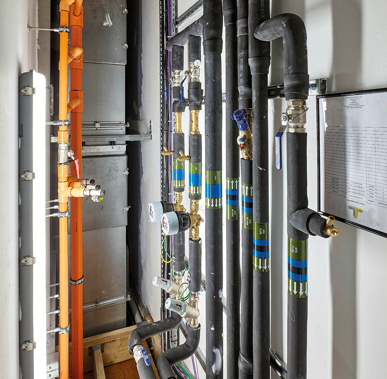
Figure 2: Example of insulated pipework that serves a building heat network
A proportion of the heat ‘lost’ from the distribution loop will increase the risk of overheating, particularly in the summer and shoulder seasons, and notably in communication spaces such as corridors. A knock-on effect is that an increasing number of residential buildings are being designed with cooling systems to overcome the problems of overheating – at least some of which may be the result of the heat being ‘lost’ from the distribution loop. (With in-home heat pumps connected to ambient loops, cooling may be provided effectively, as discussed later.) Because of the uncertainties in design, and the eventual installed detail of a building’s heat network, it is not unusual for designers to apply a ‘rule of thumb’ percentage guestimate of heat losses from a distribution network. However, BS EN ISO 122417 Thermal insulation for building equipment and industrial installations – calculation rules provides a model that can be more reliably applied to account for the key parameters that characterise the flow of heat between the water flowing in the pipe and the surrounding environment.
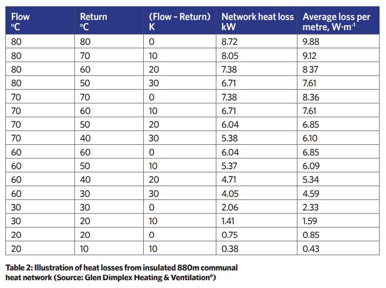
An example calculation was undertaken, employing BS EN ISO 12241, to compare the heat loss from a distribution network at different temperatures for a notional multi-residential building with 55 apartments, with the communal network length of 880m, fed from central boilers (serving HIUs) delivering a peak of 365kW to meet the demand for heating and DHW service in the apartments. Table 2 shows the calculated heat losses8 for the network at various flow and return temperature pairs, and is illustrative of the impact of changing temperatures (without varying the flowrates or pipe dimensions).
Referring to Table 2 for a typical traditional design, with flow at 70°C and return at 40°C, the losses would vary between 7.38kW and 5.38kW across the network, depending on the load and the resulting return temperatures. At the design load of 365kW, the 7.38kW loss equates to 2% of the load – probably far less than a rule of thumb might indicate, but also dependent on a consistently good standard of insulation. It is notable that the pipework heat losses at the lower flow temperatures, which are akin to ambient networks, are relatively tiny.
As recently reported9 by Wang et al, the various types of heat pump applications are likely to result in different values of diversity factors for energy demand, and further studies are needed, particularly with the increasing use of heat pumps and heat storage. For example, despite the high coefficients of performance (COPs) that would typically be achievable with in-home heat pumps, the primary energy source will be electricity used to power the heat pump compressor. Depending on the heat pump type and the arrangements for legionella control in storage cylinders, there may also be an electrical component that is attributable to the top-up heating of domestic hot water.

Figure 3: Example of an in-home water-to-water heat pump that can provide cooling as well as heating (Source: Glen Dimplex Heating & Ventilation)
A specific attribute of in-home water-to-water heat pumps, such as illustrated in Figure 3, is that they can provide cooling, as well as heating, to the space. The ambient communal loop will provide a relatively low temperature source – so giving a reasonable heat pump cooling energy efficiency ratio (EER). This arrangement also allows energy recovery if some areas in the building require cooling while, concurrently, others demand heating (for example, for DHW). If there are any common areas, commercial spaces or shared facilities – such as gyms or communal parts of the building – that employ the ambient loop, these can contribute to the mix of heating and cooling. The heat demand from a residential development could, through the ambient network, provide ‘free-cooling’ for refrigeration. Unless the cooling load is a small proportion of the heat load, it is likely that mechanical cooling input to the loop will be required. This will add to the complexity of assessing diversity of load in the network, but can deliver very significant operational gains, so reducing energy use and carbon emissions.
© Tim Dwyer, 2022