![]()
The thermodynamics of the refrigerant vapour compression cycle
The pressure-enthalpy diagram (also known as a Mollier diagram) offers a convenient way of showing the thermodynamic properties of a refrigerant, and the basic vapour compression refrigeration cycle, as shown in green in Figure 1.
In real systems, the four principal processes – compression, condensation, expansion, and evaporation – also experience pressure loss from the components, plus heat losses and gains from the ambient air, and the compression process would not be ideal, so would be more like the real cycle shown in Figure 1.
The lower the enthalpy of the refrigerant at entry to the evaporator, the greater potential there is to supply useful cooling.
Coefficient of performance (COP) and energy efficiency ratio (EER)
The simple coefficient of performance (COP) for a given vapour compression cycle is calculated by the cooling power delivered through the evaporation process divided by the work added during the compression process, as in Figure 1. In this example, the cycle has a COP of (395-250)/(430-395) = 4.1. The COP is an instantaneous measurement of the refrigeration system’s thermodynamic performance. The energy efficiency ratio (EER) is commonly used by practitioners – and in standards – as a measure of the practical energy efficiency of a refrigeration cooling cycle, and provides a ratio of useful cooling energy to (typically) electrical input energy. In SI units, this is a dimensionless ratio and is lower than the cooling COP, as it accounts for such items as motor and drive efficiencies, pressure and thermal losses. The seasonal EER (SEER) offers a standardised indication of the cooling performance accounting for application and operating conditions (there is a UK version of SEER1, as used in compliance assessment, and the European ESEER2, which apply slightly different load profiles and weightings). In heat pump applications, the term COP – together with the seasonal COP (SCOP2) – is typically used to indicate the ratio of useful heating to electrical power input.
Figure 1: A refrigeration cycle plotted on a Mollier diagram for a typical synthetic refrigerant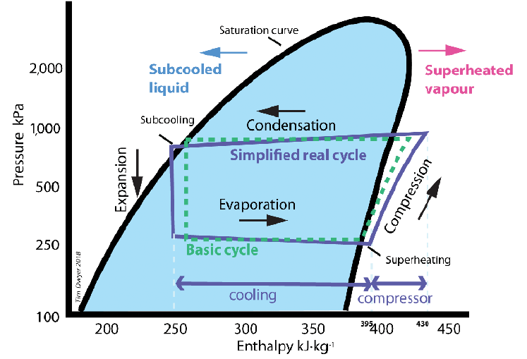
Chiller manufacturers have been focusing on reducing compression energy by developing more efficient compressor technologies – notably through the development of magnetic-bearing compressors equipped with variable-speed drives – and this has significantly improved the efficiency of the system. However, there are other elements of the cycle that can be optimised to improve its efficiency further by increasing the evaporation potential without using more compression energy. A key component is the condenser, which can be readily optimised to increase system efficiency at a lower cost than adopting some of the more advanced compressor technologies and improved monitoring and control. Advanced technologies can be combined with such optimisation to improve performance further.
Figure 2: Applying an extended condenser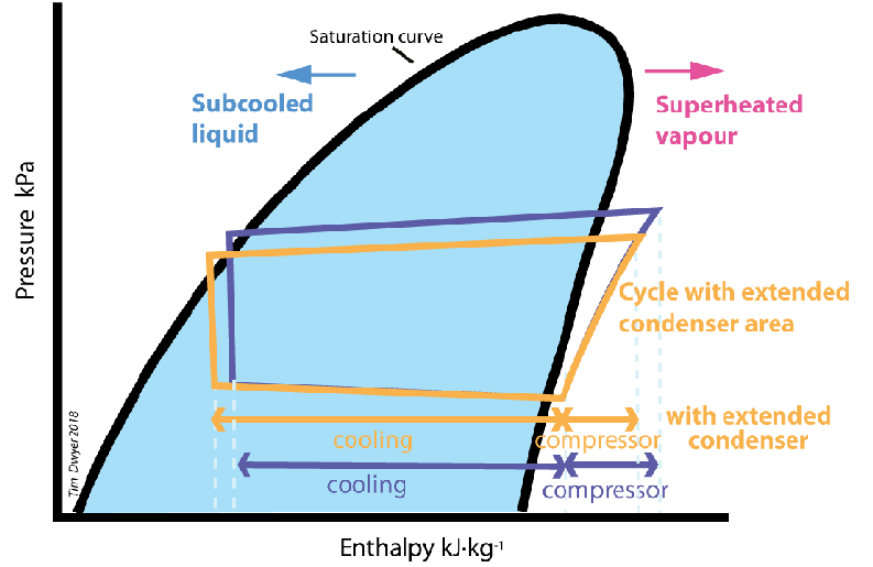
Extending the condenser process provides a greater cooling potential in the evaporating process (as shown in Figure 2), so increasing the COP and the EER. This can be achieved by reducing the condensing temperature – which will be practically limited by the ambient conditions – while still ensuring that there is an appropriate amount of refrigerant sub-cooling (typically approximately 5K) as the refrigerant liquid leaves the condenser. In many cases, there is an opportunity to achieve this by increasing the effective heat rejection area of the condenser.
Increasing the condenser heat rejection area
When considering a traditional tube and fin air-side heat exchanger, the surface area-to-volume ratio can be increased by several techniques:
■ Reducing the diameter of the tubes in the coil block and boosting the number of tubes will increase the amount of heat exchange. This works well but raises the cost and weight of the coil block.
■ Increasing the number of fins per length of tube will also improve heat exchange, but this will have adverse effects:
- The air-side pressure drop of the coil block grows and requires more fan power to move the same amount of air
- The coil can trap more debris, therefore reducing airflow and limiting heat transfer
- It will increase the cost and weight of the coil block
■ Reducing the thickness of the tube wall to increase coil U value – although this weakens the structure of the coil and makes it more prone to damage
■ Selecting different materials with improved thermal conductivity will improve a coil’s heat exchange performance – for example, copper has a greater thermal conductivity than aluminium, therefore coils with copper tubes and fins offer greater levels of performance. However, copper is around three times the price
of aluminium.
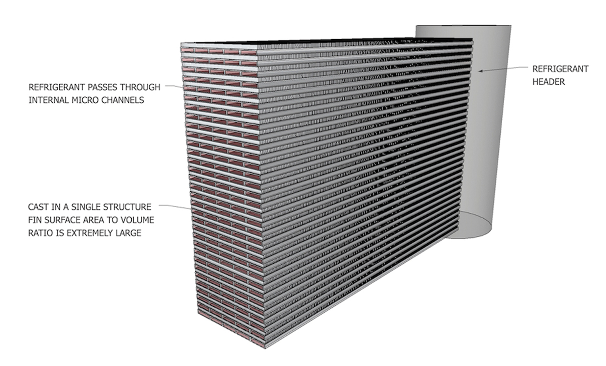
Figure 3: Example of a plate fin heat exchanger (Source: Rob Young, Cooltherm)
An increasingly common alternative is the plate fin heat exchanger (Figure 3). They were originally developed in the aircraft industry in the early 1960s and offer a bigger surface area to volume ratio, while cutting weight, increasing structural strength, and reducing air-side pressure drop. Although initially prohibitively expensive for general applications, production costs fell as they were more widely adopted by the chemical and automotive industries to meet the requirement for robust, highly efficient coils for use in the aggressive environments. Subsequently, these have been applied by the chiller and air conditioning industry, often referred to as brazed aluminium microchannel (BAM) coils. Microchannel heat exchangers provide high refrigerant convective heat transfer coefficients and a greater wetted surface to volume than conventional heat exchangers. Microchannels can, however, also potentially increase the pressure drop associated with the smaller flow passage – although this can normally be resolved by a careful design ensuring sufficient cross-sectional flow area. In addition, the flow-length inside microchannel heat exchangers are typically much shorter for a given duty, which will reduce their overall pressure drop.3 An additional advantage of this type of heat exchanger is that there is typically 70% less refrigerant volume in the heat exchanger, and the air-side static pressure resistance through the coil is half that of a traditional tube and fin heat exchanger. The single-cast aluminium structure also makes the coil comparatively strong.
Until recently, large chiller condenser coil configurations (and specifically BAM coils) were limited to linear, flat coil designs, generally arranged in a ‘straight’, ‘W’ or ‘V’ section configuration (as shown in Figure 4). Tube and fin condenser coil designs have been limited either to being straight or curved with long radius bends, as often found on small split DX air conditioning systems, with the condenser face on two or three sides of the unit. A curved tube and fin condenser is difficult and expensive for larger systems (such as industrial water chillers), so until now curved coils have only typically been found on small systems.
Circular BAM coils
BAM condenser coils are robust, and the cast-metal construction allows them to be shaped more easily than traditional coils, so they can be manufactured with tight radius bend configurations. This has recently allowed the creation of completely circular large-scale condenser coils, that – compared with traditional ones – can increase the chiller output by allowing a larger coil face area to be installed in the same frame dimensions. Linear BAM condenser coils are typically applied across the width of the chiller in a ‘V’ configuration (as in Figure 4), with the most common large-scale chiller width being 2.25m (limited by truck trailer widths), which typically limits a condenser coil width to approximately 2m.
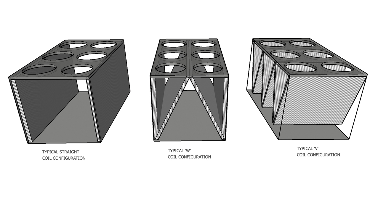
Figure 4: Common condenser coil configurations (Source: Rob Young, Cooltherm)
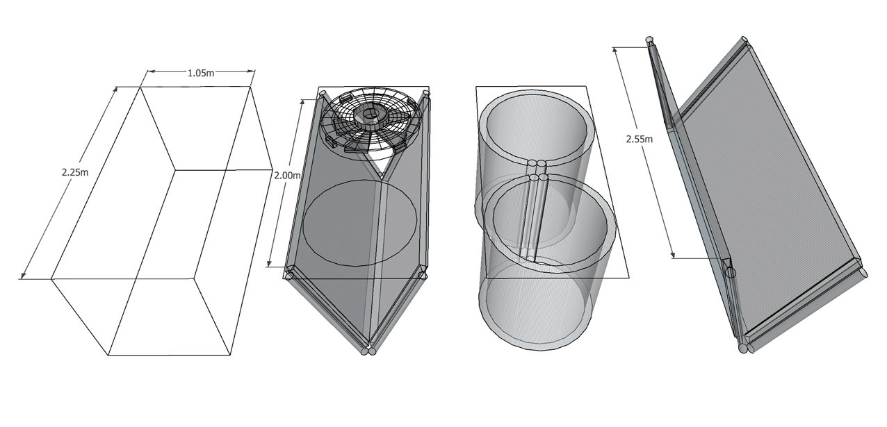
Figure 5: Example comparison of applying circular designs (Source: Rob Young, Cooltherm)
Employing a circular design allows more coil to fit into the same frame. Each coil is 27% longer and, for example, almost 10% more coil face area is gained over the previous most efficient use of space in the ‘W’ condenser coil configuration (as shown in Figure 5 and Table 1).
This offers the opportunity to cut the chiller footprint for the same capacity. It also assists in compensating for the general industry practice of moving away from cooling towers, which tend to be more compact than air-cooled chillers per kW of cooling.
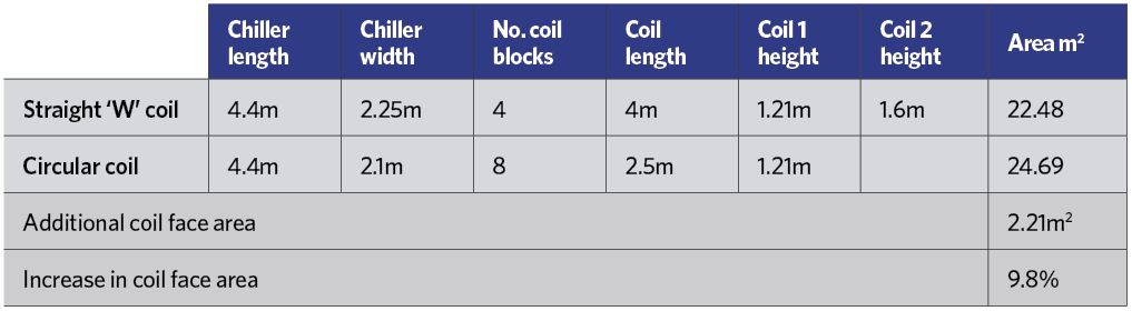
Table 1: Comparison of the effective area linear ‘W’ configuration, and circular, BAM condenser coils (Source: Rob Young, Cooltherm)
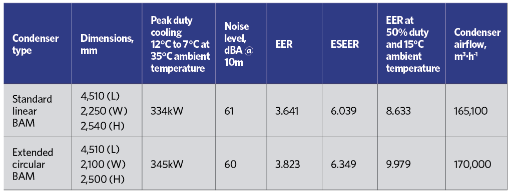
Table 2: Comparison of linear and extended circular BAM condensers for example refrigeration system (Source: Performance data – Geoclima and Rob Young, Cooltherm)
Real-world application and performance
The availability of circular format condensers has allowed the recent development of a circular BAM condenser coil machine that also employs a compressor with magnetic-bearings. The comparison in Table 2 is for two systems where only the condenser is different. The core system has a flooded evaporator, charged with HFO R1234ze refrigerant, employing a Turbocor TT310 compressor and 800mm EC condenser fans.
The comparison indicates that the system employing the circular BAM condenser shows improvements across all aspects, with a 5% improvement in the seasonal EER and a 15% improvement at conditions relating to 50% full load and a typical UK ambient temperature of 15°C. So, taking an example application with an average cooling load of 150kW, occupied 12 hours a day, five days a week, 52 weeks of the year, a system employing a circular BAM condenser could reduce operational energy use by 3.7MWh. This would also save more than a tonne of associated CO2 emissions (based on the ESEER figures).
By applying generously sized and appropriately configured air-condenser coil formations within the same chiller frame – regardless of coil type and compression – the amount of energy a chiller consumes can be reduced. If this is done within the same – or smaller – chiller footprint, these energy savings can be achieved with little increase in the initial chiller cost. If the cooling load is maintained but the air-side heat rejection surface area increases, then less fan power is needed to reject the energy and, consequently, noise can also be reduced.
© Tim Dwyer, 2018.
■ With thanks to Robert Young for his contributions to this article.
References:
- Non-Domestic Building Services Compliance Guide: 2013 Edition.
- BS EN 14825: 2016 Air conditioners, liquid chilling packages and heat pumps, with electrically driven compressors, for space heating and cooling.
- Wanh, H, Performance enhancement of a thermally activated cooling system using microchannel heat exchangers, Applied Thermal Engineering, Volume 31, Issues 14–15, October 2011, pages 2,951-2,962.