![]()
The term ‘domestic’ hot water can be somewhat confusing, as it includes any ‘water that has been heated for cooking, food preparation, personal washing or cleaning purposes, and the term used irrespective of the type of building in which the hot-water system is installed’.1 DHW would normally be ‘wholesome’A water, so it is equivalent quality to that used in the drinking water services but at a higher temperature. The amount of hot water required, and the pattern of consumption, will depend on many factors including: the application (for example, residential, commercial or institutional); the users (owners, public, visitors or employees); the outlet types (such as combinations of spray basin taps, bath taps, showers, sluice buckets, washing machinery, and so on); the system characteristics (single or multi-point, extent of dead legs, distribution distance and recirculation method); and the degree of automation and control. The range of parameters and their uncertainty makes the prediction of hot-water usage particularly challenging. The guides and tables that have been produced to assist in design are based on historical measurements of actual hot-water consumption in various applications, so will not necessarily reflect the use of any particular building.
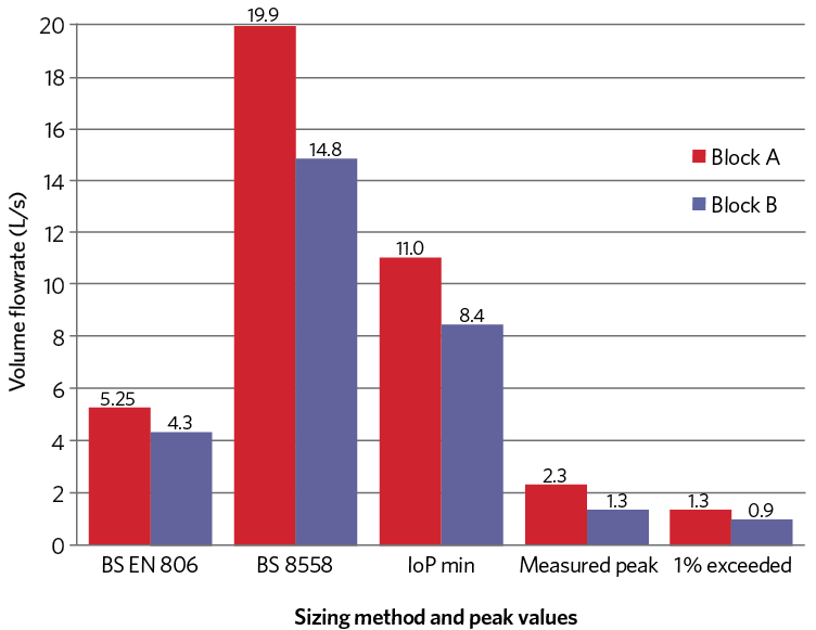
Figure 1: Examples of measured v predicted water consumption (combined hot and cold) for two UK residential apartment blocks, as reported by Tindall
Typically, the design profile for hot-water use is established by using loading units (LU) that provide a statistically based prediction of the required flow of water. But, as discussed in Jess Tindall’s paper2, the LUs between the three principal methods employed in the UK – BS EN 8063; CIPHE Plumbing Engineering Services Design Guide (IoP)4; and BS 85585 – differ in their bases. Unlike BS EN 806, the IoP and BS 8558 LUs are not simply linked to flowrate, but also take account of the length of time that the outlet will be in use and the outlet’s patterns of usage. All three methods sum the downstream LUs for each pipe section, and then employ a conversion chart to determine the design volume flowrate (the charts are based on different levels of diversity). CIBSE Guide G6 gives a detailed commentary – and employs the IoP LUs – but the potential difference in design sizing is significant, as indicated in the example comparison undertaken by Tindall and reproduced in Figure 1.
Power water heating
Energy to heat one litre of water – To heat 1L (1kg) water from 8°C to 60°C the energy required = 1kg x 4.2kJ·kg-1·K-1 x (60-8) = 218kJ (0.061kWh).
Power required for a flow – To continuously heat a flow of 1L in one second requires a power of 218kJ·s-1 (218kW) to 60°C and 155kJ·s-1 (155kW) up to 45°C (direct outlet temperature or mixed, for handwashing). And to heat 1L in n seconds from 8°C to 60°C would require
(218kJ ÷ n)kW.
End energy use example – A 100L (100kg) bath would be around
40°C (by mixing 60°C and 8°C water) and so would require 100kg x 4.2kJ·kg-1·K-1 x (40-8) = 13,440kJ (3.73kWh) at point of use (that is, no distribution losses included).
This highlights not only the uncertainties in the prediction of required water supply, but also the impact of the diversity factors that are employed by the methods – BS EN 806 applies more significant diversity factors at high values of LU. However, as noted in Guide G, in practice in buildings with large numbers of sanitary fittings, a small increase in demand over the design level is likely to cause a slight reduction in pressure and flow at the fittings in use, which is unlikely to be noticed by the users unless this becomes excessive. Whatever the variability is, the hot water generator and the system must be sufficiently flexible to meet that demand with a safe supply.
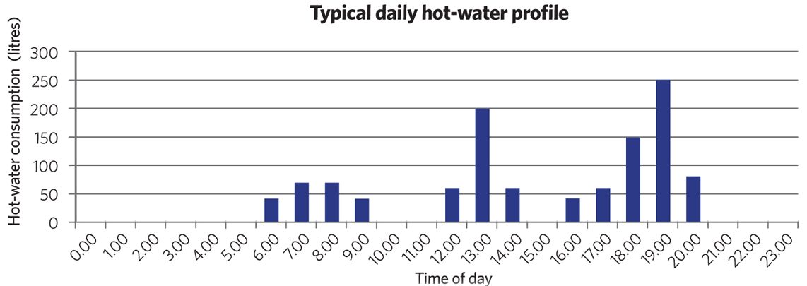
Figure 2: Example hot-water demand that could be experienced
Serving the variable DHW needs
The system needs to be able to produce the required volume of (controlled temperature) hot water at the rate required – and at an appropriate pressure – at the point of use. As the UK average electricity cost, for medium size businesses, is currently about five times that of gas7, and the equivalent CO2 emissions for grid-supplied electricity are about 1.75 times that of gas8, the use of gas is the most commonly chosen energy source for hot-water generation systems. (Electricity is also a high-quality form of energy, and in terms of exergy is not most productively used in generating DHW.) Heat pumps, and systems that employ heat rejected from local generation, industrial and commercial processes and environmental systems – when appropriately applied – can often provide a viable and operationally effective electrical alternative to using natural gas.
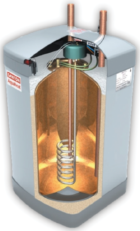
Figure 3: Example of multipoint electric water heater with integral storage that could be installed under a worktop or in a cupboard and could, for example, serve one or two washrooms. Efficiency is very high and practically only affected by standing losses of less than 1kWh per day
Figure 4: An indirect storage calorifier that includes coils to heat the stored water using primary, higher temperature, hot water from a heat source (Source: Andrews Water Heaters)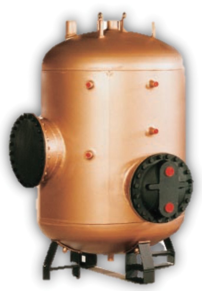
Where natural gas is not available, or is impractical – and, possibly, where the system is likely to be used for a short period or there is local renewable power generation – direct electricity can offer a flexible cost-effective solution. For example, at its simplest, this could be a point-of-use, non-storage, instantaneous electrical heater serving an individual outlet. However, aside from discrete applications – such as single basins serving, for example, lone WCs in a shop or warehouse that have no other significant hot-water need – the practicality of this system may not be appropriate to being scaled up to multiple installations in a building because of factors such as maintenance, power distribution and loading, aesthetics, and limited hot-water flowrates. The flowrate through a small basin mixer tap is approximately 0.05L·s-1 and would require 7.75kWe (32A @ 240V) to supply water directly at 45°C.
To allow water generators (electrically and gas-powered) to benefit from the typically intermittent hot-water demand – as in the example in Figure 2 – it has been the norm to use some form of hot-water storage.
Moving energy
Natural gas pipework is able to distribute large amounts of energy using a relatively small space. For example, a 25m length of 2in nominal diameter (60mm outside diameter) steel gas pipe – weighing 5.5kg per metre – could supply approximately 310kW.
To meet the same load, single-phase electricity would theoretically need two conductors, each in 120mm diameter cables (and each weighing about 20kg per metre), plus earthing.
This can either have an integral heater, such as in the multipoint heater of Figure 3, by using a separate hot-water storage vessel or a calorifier that – as well as storing hot water – uses a coil carrying hot fluid or an electric element to heat the water (as in Figure 4, but shown without the essential insulation). This allows the stored water to be heated with an indirect power source (typically a boiler) that, when intermittently used, can deliver an adequate volume flow to meet the full demand. However, the DHW would need to be stored at a temperature of at least 60°C, requiring primary water at (typically) 80°C flow and 60°C return – this would not allow a boiler to operate in condensing mode.
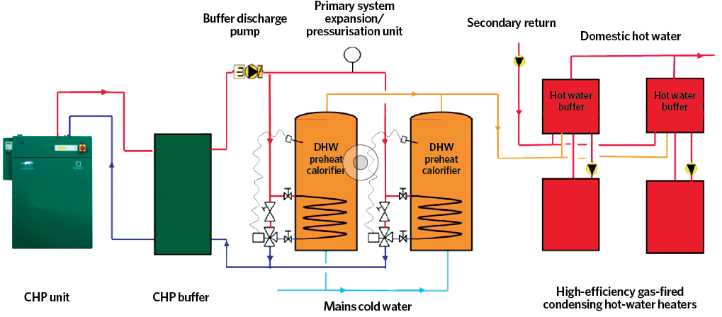
Figure 5: Employing storage to maximise the operating time of a CHP plant through preheating the DHW that is subsequently heated by high-efficiency direct gas-fired condensing water heaters (Source: Andrews Water Heaters)
Whenever water is stored, due consideration must be given to preventing risks from Legionella (see CIBSE TM13: 2013 Minimising the risk of Legionnaires’ disease). The recovery time – the time to heat the water up from the inlet temperature – will normally be indicated by manufacturer (accounting for losses), but can also be readily estimated using the calculations illustrated in the ‘Powering water heating’ panel.
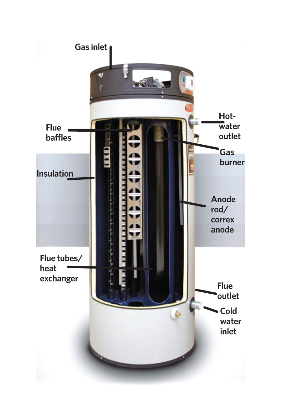
Figure 6: A direct gas-fired storage hot-water heater (Source: Andrews Water Heaters)
A storage vessel plays a key part in an integrated hot-water system where the water may be heated from multiple sources, including combined heat and power (CHP); a heat pump; or heat recovered from environmental systems – such as variable refrigerant flow (VRF) – and renewable or industrial processes.
Such a vessel can also be used to pre-heat water (below DHW temperatures), so maximising the opportunity of recovering heat from lower temperature sources, and it is subsequently heated to the required supply temperature in a hot-water generator. This not only helps to reduce the total primary power requirement to produce hot water, but can also allow other systems to work more effectively.
For example, the CHP in Figure 5 will be able to operate for longer hours (to generate electricity), so improving its cost and environmental effectiveness, as well as reducing the load on the hot-water generators. The smaller buffer vessel is provided as part of the CHP unit to reduce cycling and provide primary control feedback to ensure safe and efficient operation. The thermal storage is provided by two preheat calorifiers that then supply the water to the condensing high-efficiency water heaters.
A direct gas-fired storage hot-water heater – as in Figure 6 – provides hot water at high generating efficiencies, and the relatively low storage capacities enable very short recovery times. However, as it is a storage vessel, it can be selected to meet intermittent peak DHW demands while having a modest input power. There are similar electrically heated cylinders available, but they, typically, will have lower power inputs and so longer recovery times.
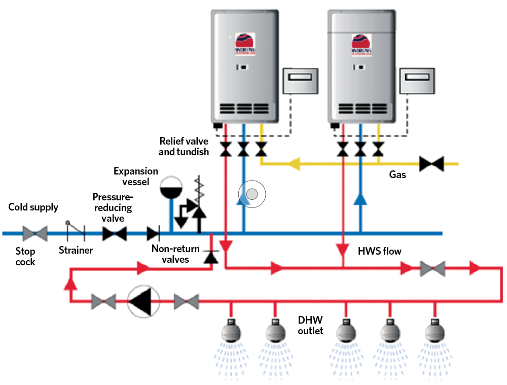
Figure 7: Non-storage, high-efficiency continuous-flow water heaters combine to meet instantaneous hot-water load. The 0.26L·s-1(Δθ=50K) 90% efficient heaters are wall-hung and 615mm high, 465mm wide and 240mm deep (Source: Andrews Water Heaters)
Gas-distribution systems – and so gas-fired systems – are able to deliver large amounts of energy in small spaces (see ‘Moving energy’ panel). The non-storage, high-efficiency continuous-flow water heaters in Figure 7 heat incoming mains water directly by using multiple parallel connected units. These can supply hot water continuously at their maximum design flowrate – as well as modulate to part-load – to provide a compact hot-water generator with no requirement for storage, with its associated losses and maintenance requirements.
© Tim Dwyer, 2018.
References
- England Building Regulation Approved Document Part G Sanitation, hot-water safety and water efficiency, 2015, amended 2016.
- Tindall, J et al, A comparison of UK domestic water services sizing methods with each other and with empirical data, Building Services Engineering Research & Technology 2017, Vol 38(6) 635–649.
- BS EN 806 Specifications for installations inside buildings conveying water for human consumption, BSI 2006.
- Plumbing engineering services design guide, CIPHE 2002.
- BS 8558:2015 Guide to the design, installation, testing and maintenance of services supplying water for domestic use within buildings and their curtilages – Complementary guidance to BS EN 806, BSI 2015.
- CIBSE Guide G Public health and plumbing engineering Chapter 2, CIBSE 2014.
- Prices of fuels purchased by non-domestic consumers in the UK, UK Government BEIS, December 2017.
- UK Government GHG Conversion Factors for Company Reporting, UK Government BEIS, 2017.