![]()
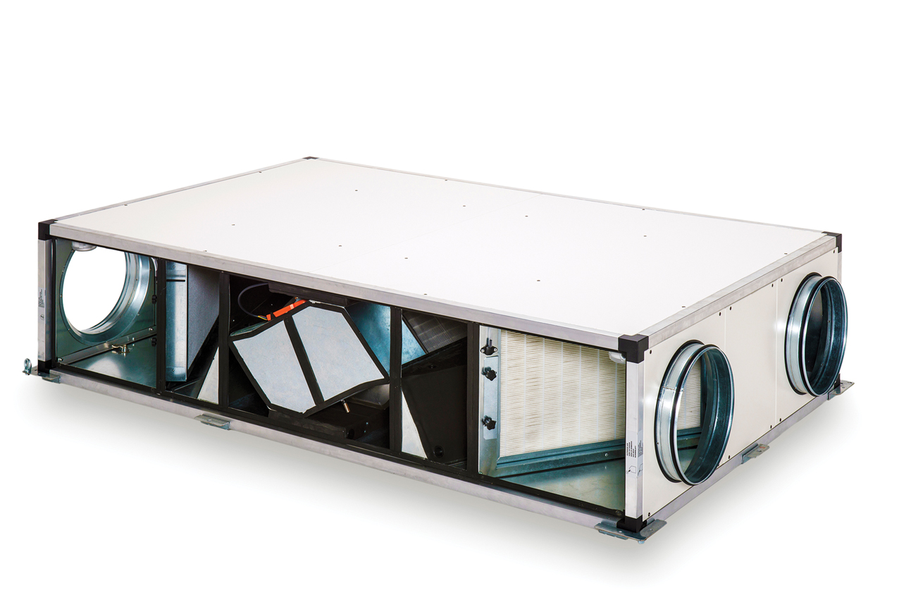
Figure 1: MVHR unit designed for installation in ceiling void (Source: S&P)
The MVHR unit, as shown in the photograph in Figure 1, is designed to fit above a false ceiling in the ceiling void. These units tend to be as compact in height as possible, and the access to service filters and heat exchangers is usually from the side, as ceiling access panels are unlikely to be large enough to allow bottom panels to be removed. An unanticipated effect of the Ecodesign directive1 on such non-residential MVHR units – classified in the regulations as ‘bidirectional ventilation units with heat recovery’ – is that the unit size has increased relative to the air flowrate. This is to meet the combination of:
■ More stringent specific fan power (SFP) requirements. Larger, typically backward-curved centrifugal or plug fans, operated at slower speeds, normally perform better than smaller fans
■ Higher required heat recovery efficiencies. The smaller compact cross-flow heat exchanger is likely unable to meet the minimum 67% effectiveness requirement (rising to 73% in January 2018)
■ Lower permitted sound power levels – so requiring motors with lower sound output and increased sound insulation.
Larger sizes of electro-commutated (EC) fans have been developed to suit higher airflows and duties, but are still able to fit into the restricted space available in these limited height units.
The other commonly employed MVHR configuration, as shown in the unit in Figure 2, is free-standing. The unit is assembled on a more robust chassis and is likely to be installed outside, with a weatherproof cover or in a dedicated plant room.
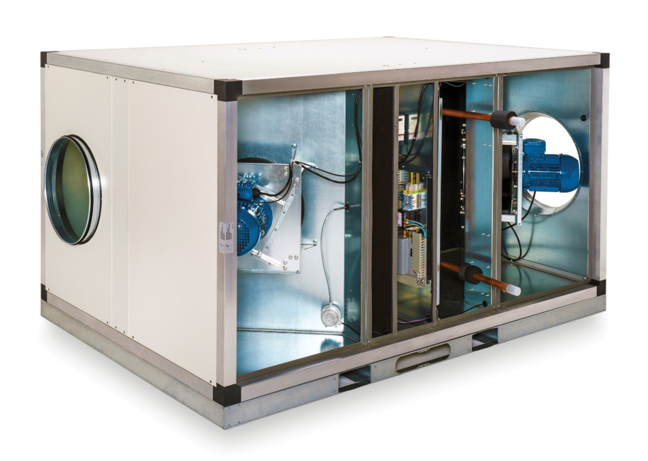
Figure 2: AHU suitable for plant room or rooftop installation (Source: S&P)
Both construction types usually have insulated panels that allow a certain degree of flexibility, so that ducting connections can be swapped between side and end panels for convenience.
Controls and heating options are commonly integrated for ease of installation. Other modular elements can also be added to standard configurations to integrate heat pumps and more specialist filters, to deliver higher standards of indoor air quality (IAQ).
The units typically incorporate additional heating capacity to make up the difference between the recovered heat and the required supply air temperature.
There are numerous heater options available, including electric heater batteries, LPHW heating coils and refrigerant condensers, as well as reversible coil options to provide a capability for chilling and heating, plus heat recovery. Heat pumps may be used by employing a refrigerant coil that could be used for cooling or heating – in these cases, the control of the refrigerant section is normally supervised by the heat pump unit, with the MVHR coil control acting as a slave. This can be integrated with other variable refrigerant flow systems in the building, creating high operating efficiencies by effectively using otherwise rejected heat.
Since these units are designed to provide ventilation, air filters are included – not only to protect the equipment, but also to ensure that a reasonable quality of air is supplied to the room. Aside from the larger particulate contaminants in the outdoor air, buildings that are located in urban areas are also likely to be subject to higher levels of PM1, PM2.5 and nitrogen dioxide (NO2), resulting particularly from vehicle emissions and combustion in heating appliances.
A standard ‘F7 grade’ filter (approximately equivalent to ISO 16890 ePM2.5 80%) will reduce2 PM2.5 particulates by approximately 80%, and PM1 by 50%, but upgrading to an ‘F9 grade’ (approximately equivalent to ISO 16890 ePM1 80%) will eliminate greater than 90% of PM2.5 and 80% of PM1 particulates cost effectively. However, it will increase the pressure drop and resulting fan power and these filters will not filter out NO2. This requires an additional filter – such as an active carbon filter – as an effective means of reducing high NO2 to an acceptable mean annual concentration level of 40μg·m-3. These filters are typically fitted adjacent to the heat recovery unit and, as a dividend, also offer additional acoustic attenuation. They will significantly add to the weight of the unit and to the required fan power.
Integration of thermal wheels into MVHR
The thermal wheel (variously known as heat wheel, rotary heat exchanger, energy or enthalpy wheel) is based around a rotating cylinder that is packed with an air permeable material. The packing is designed to provide a large surface area for the transfer of heat between the airstream and the material. The wheel is positioned in a casing, so that one half of the wheel sits in the airstream carrying outdoor air, while the other half is in the air being discharged from the conditioned space. As the wheel is driven around by a small motor, it first transfers energy between the discharge airstream and the packing – for example, as the air is extracted from a room, its temperature reduces as it passes through the packing – and then as the wheel rotates into the supply airstream, the energy is exchanged to or from this air – for example, incoming outdoor air is heated.
The heat transferred between the two airstreams may be sensible heat, leading to a change in the dry bulb temperature in the two streams or – more effectively – when the wheels are hygroscopic, include both latent heat and sensible heat, so affecting both the dry bulb temperature and the air moisture content as shown in Figure 3.
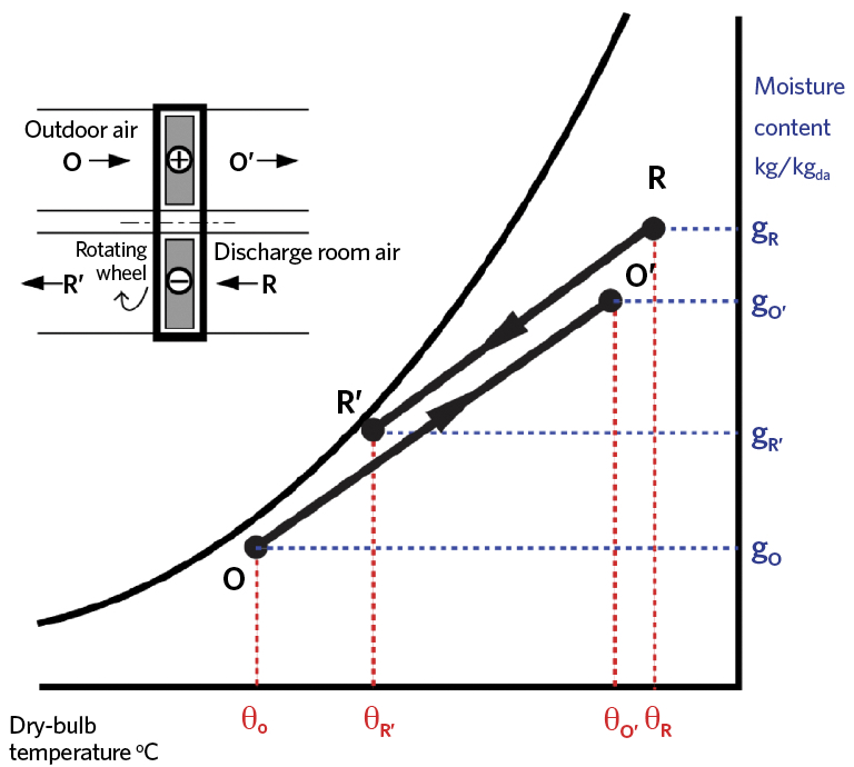
Figure 3: The psychrometry of the total thermal wheel
Thermal wheels are able to provide high-efficiency heat recovery in a compact form. Despite the relatively short time that the air takes to pass through the wheel and the relatively low pressure drop across the wheel, the heat recovery efficiency can still be more than 80%. Wheel diameters can be as big as 4m without compromising performance and efficiency, so can be used with high airflow rates. Since thermal wheels can be designed to transfer latent energy between airflows, this can negate the need for humidification of the incoming dry winter air and also eliminate the need for condensate drains. The amount of heat transferred may be readily regulated by varying the speed of the rotating wheel.
Wheels can also be coated in silver or gold for sterile environments, such as hospitals. Cross-contamination can occur by carryover, as air entrained within the wheel is transferred to the other airstream, and leakage. A purge section would normally be installed to reduce carryover, and this can also be minimised by avoiding large pressure differences between the two airstreams. Hygroscopic media may transfer toxic gases or vapours from a contaminated exhaust to a clean air supply.3
Under the Ecodesign directive, a thermal bypass is required for MVHR units. When employing a thermal wheel, the thermal bypass is achieved by simply stopping the rotation of the wheel. Dependent on the application, a small ‘ducted’ bypass around the wheel can provide reductions in fan energy for when the wheel is stopped. In some applications – for example, where there is some room cooling – it may be advantageous to operate the wheel (without using a ducted bypass) for the majority of the year.
Multi-mode control
Modern packaged MVHR systems would normally be supplied with manufacturer-installed controls that can be used to set up different ventilation modes relatively quickly. The majority of current designs have inbuilt pressure, airflow and temperature sensors, and are able to connect with external sensors to provide control regimes according to the particular requirements of the building.
So, for example, a constant air volume configuration would allow a single zone or area, such as an office, to have a continuous volume supply regardless of the cleanliness of filters, damper settings and outside air pressure. (It would be normal for the unit to provide feedback to the user if, for example, the filters required attention.) Demand-led control can be applied for zones or rooms – such as meeting rooms – that have variable occupancy, where volume flows are linked to air quality sensors or occupant counters.
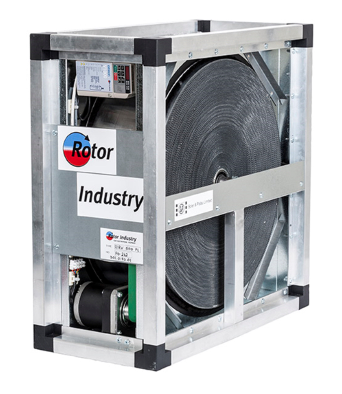
Figure 4: Example of thermal wheel (Source: S&P)
Such systems are increasingly being applied to supply multi-zone systems that include a combination of constant and variable air volume requirements. These can be delivered with a single unit that will provide a constant pressure and variable airflow to the ventilation system – based on feedback from zone sensors and control – by variable geometry air diffusers and dampers. Before the advent of EC fans and low-cost integrated controls, such systems would have taken a considerable period to commission and set up. Having designed and installed the system, it can provide multi-zone mixed-mode control with a simple selection of the appropriate control scheme to suit the building or space to be ventilated.
The integral controller would normally be capable of interfacing to the building management system (BMS) through a standard protocol (such as BACNet, Modbus or LonWorks) to allow commissioning and operation, as well as communication with other building systems, and to provide ongoing adjustment, monitoring and reporting.
Enhanced Capital Allowance
Under the UK government’s Enhanced Capital Allowance Scheme4 (ECA), energy-saving products that are approved and listed on the Energy Technology List5 offer businesses the opportunity to write off the whole cost of the equipment against taxable profits in the year of purchase. The ECA scheme is surrounded by myths and misconceptions that date back to the early 2000s, when inverters and more efficient motors were the first eligible technologies. In those early days, only the costs of the approved component to a system could be claimed, but because these costs were not readily isolated by equipment manufacturers it was rare that claims were made. In addition, the paperwork accompanying a claim was onerous and time-consuming to complete. Now, most companies fill in a self-assessment corporation tax return on a quarterly basis and the process of claiming ECAs is simply a matter of deducting the eligible amount from the calculated corporation tax due figure.
In the category of air-to-air energy recovery products, those approved using thermal wheel rotating heat exchangers are eligible to offset the full purchase value against corporation tax in year one – that includes the invoiced price of the product, delivery, installation and commissioning costs.6 This contrasts with other heat-recovery technologies, such as plate heat exchangers, where only the cost of the exchanger itself can be claimed.
To ease the integration of all the elements into the MVHR unit, several manufacturers will offer online tools that allow selections to be made quickly. These are often linked to quotations, technical datasheets, compliance information – such as specific fan power (SFP) data – graphical and BIM-related files.
© Tim Dwyer, 2017.
■ With thanks to Alasdair Howie of S&P for providing core information for this article.
References
- Commission Regulation (EU) No 1253/2014 of 7 July 2014 implementing Directive 2009/125/EC of the European Parliament and of the Council with regard to ecodesign requirements for ventilation units.
- PM1 – Fine dust hazard to health, Camfil, www.camfil.com
- CIBSE Guide B2, Ventilation and Ductwork, Section 2.3.4.3, CIBSE 2016.
- www.gov.uk/government/publications/enhanced-capital-allowance-scheme-for-energy-saving-technologies – accessed 9 October 2017.
- etl.beis.gov.uk/engetl/fox/live/ETL_PUBLIC_PRODUCT_SEARCH – accessed 9 October 2017.
- ECA272 Capital Allowance v7 April 2015 page 4, www.gov.uk/government/uploads/system/uploads/attachment_data/file/323611/hs252.pdf – accessed 11 October 2017.