
Chilled beams deliver cooling to rooms primarily by using cool water in coils that exchange heat with room air, so reducing the air dry-bulb temperature. The principal advantage of using a chilled beam – as opposed to an ‘all air’ air system – is that moving heat around a building can be undertaken far more efficiently by pumping cool water in pipes than by moving the same amount of heat in ducted air. This is, of course, the advantage of any distributed hydronic ‘terminal unit’ system, including fan coils, induction units, convectors and radiators. The simplicity of the premise that underpins the fundamental advantage of such systems potentially obfuscates other – for the most part – equally simple design and operational characteristics that can provide significant life-cycle energy and carbon savings. This CPD will explore some of these designs and applications for chilled beams.
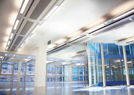
Image 1: Multi-service chilled beams
A brief outline of chilled beam technology
Chilled beams are mounted at high level in the conditioned space (principally in commercial buildings), and can be fully encased and suspended from the soffit or integrated into a false ceiling. Known as ‘passive’ or ‘active’, both types have coils that carry cool (or chilled) water that exchanges sensible heat with warm room air, as the air passes across and between the cooler coils (and their extended surfaces). In all cases, the temperature of the surfaces of the beam must not fall below the dew-point temperature of the surrounding air, otherwise condensation is likely – any dehumidification (or latent cooling) must be undertaken with an associated air supply system.
Passive chilled beams (Figure 1) rely on natural convection currents in the room, driven by denser cool air being drawn downwards by gravity, so displacing the less dense warmer air to a high level, where it meets the cool coils of the chilled beam.
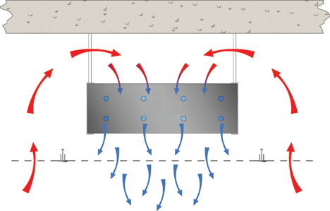
Figure 1: Simplified passive chilled beam mounted above perforated ceiling1
Active chilled beams (Figure 2) are supplied with ducted ‘primary’ air from a centralised system that will often be used to meet the ‘fresh’ air requirement in the space. This air will also provide any dehumidification required for the conditioned space by having a supply air moisture content set at a level to offset the latent loads in the space. To prevent condensation, the resulting room air dew-point temperature must be lower than the temperature of the surfaces of the chilled beam.
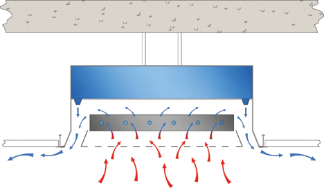
Figure 2: Simplified example of two-way active chilled beam1
The primary air is supplied through nozzles directed towards the outlet of the beam casing that induce room air up from the room (possibly via a ceiling void) and through the cool coils, to be entrained into the stream of fast moving supply air. The induction acts to increase significantly the velocity of the room air (as well as its volume flow rate) passing across the coils, so improving the heat transfer to the room air. The diffusion is enhanced by employing the Coanda effect to move the air across the room, so ensuring reasonable throws. The recommended supply air volumes for cooling can be up to 23 L·s-1 for each active metre for two-way throw beams (11.5 L·s-1·m-1 for one-way throws).1
Active ‘chilled’ beams may also be used as heating sources when supplied with low temperature hot water (water temperature less than 50°C, to moderate air stratification) in place of cool water, and utilising warm primary air.
Multi-service chilled beams (MSCBs) integrate other services into the chilled beam casing – such as ducts, lighting, cabling, audio equipment and sensors. As shown in the photograph on the previous page, they can provide an alternative to using additional trunking, or possibly alleviate the need for a ceiling service void, and may be fitted directly to the soffit, typically to provide complete lighting and ventilation supply.
There are hybrid systems (Figure 3) that also incorporate a room-facing cooled surface to provide radiant heat exchange to the room, in addition to the conducted heat exchange to the air passing through the coils and across the extended surfaces.
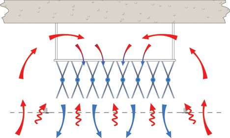
Figure 3: Hybrid passive beam incorporating significant radiant output1
The performance of a particular chilled beam will be determined by the coil-to-air heat transfer; the free area for room air flow; the temperature and flow rate of the coil water; and, in the case of an active unit, the quality, volume flow and induction capability of the primary air supply, and the resulting throw/diffusion of the air. The radiation characteristics and exposure of the hybrid beams will determine the radiant heat transfer. The amount of air supplied into the space – whether through an active beam or via a separate system – will provide the fresh air requirement, as well as latent cooling, and may well supplement the sensible cooling provided by the chilled beam.
To deliver best operational energy performance, a fundamental rule when designing chilled beam cooling systems is to ensure that the beams deliver the majority of the cooling via the water circuit. The primary air flowrate is determined to meet the air quality requirements, as well as cope with the space latent gains. Optimising the primary air requirements will improve energy efficiency while ensuring indoor thermal comfort. Performance of hybrid radiant beams will depend on the radiant ‘view factor’ to the surfaces and occupants.
Dedicated chillers and free-cooling circuits
Since chilled beams only provide sensible cooling, any latent cooling is supplied through the primary air. To maintain a reasonable room dew-point temperature – and so percentage saturation – the cooling coil in the central air conditioning plant (supplying the primary air) will need to be at a temperature somewhat lower than that of the coils in the chilled beams. Historically, it has been common for the system to be designed with the same chiller providing chilled water to the air handling unit (for fresh air supply dehumidification) and, using a mixing circuit, to maintain a higher supply water temperature – typically 14°C to 18°C – to the chilled beam circuit.
If these two systems are partially or completely separated, there are opportunities to produce higher temperature chilled water for the chilled beams. Using a dedicated chiller for the chilled beams will improve its operating coefficient of performance (COP), as the evaporator temperature will rise. By using separated cooling circuits, there may also be opportunities to use ‘free cooling’ during mid- season and colder seasons by simply circulating the chilled beam water through external coils, or employing evaporative cooling on that external circuit to bring the chilled beam water supply temperature down to approach the external wet- bulb temperature.
Weather-compensated chilled beams
Modern chilled beams can provide higher cooling levels compared with earlier models, so it is possible – and beneficial in energy terms – to increase the summer design chilled water flow temperature while still maintaining cooling capacity. Results from a recent modelling exercise2, based on four office building types located both in London and Birmingham (Figure 4), indicated that there was significant reduction in annual energy costs by allowing the flow water temperature to rise while still maintaining internal design conditions.
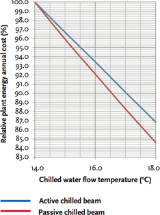
Figure 4: The effect of flow water temperature on total energy consumption of a modelled chilled beam installation for a constant load
By using weather compensation control, the chilled water flow temperature can be set based partly on the outdoor conditions. This will allow the temperature to rise (above that required at peak design) for the majority of its operational life. This will, of course, lead to higher refrigeration system COPs and additional opportunities for free cooling.
Raising the acceptable room dry-bulb temperature by lowering the radiant temperature
There may be energy savings if hybrid radiant chilled beams systems are used. These can provide 40% radiant cooling (60% convective) that will affect the mode of heat transfer to the room air, surfaces (and occupants), and so alter the constituent components of the environmental and operative (comfort) temperatures.
In a typical commercial office, the operative temperature = 0.5 x (dry-bulb air temperature + mean radiant temperature). So, by providing a low temperature surface, the hybrid chilled beam will reduce the room mean radiant temperature, so allowing an increase in room air dry-bulb temperature while maintaining constant operative temperature. This will allow the supply air temperature to rise – with a consequent potential improvement in COP – and will affect the balance of cooling loads inthespace. The actual effect on the overall room-cooling load will be dependent on the particular room design and ventilation rate.
Maximising usable building volume by applying multiservice chilled beams
Since MSCBs can be used directly on the structural soffit, they can negate the need for a dedicated ceiling void. Traditional construction would typically employ a floor-to-floor height of 3.7m. This allows for a 300mm deep floor slab, 100mm floor void and a 500mm deep ceiling void for services, while maintaining a minimum 2.8m floor-to-ceiling height. Taking a very simplistic example, a 40-storey building would have a height of 148m, whereas with MSCBs, a proportion of the space allowed for the 500mm ceiling void could be removed. At the extreme case, this could reduce the overall building height by 20m or allow an extra six floors within the same overall construction height. This would significantly reduce the relative carbon impact of the building.
Accessing ‘thermal mass’ with hybrid radiant beams
If a hybrid radiant beam system is installed with access to exposed thermal mass – such as a concrete soffit – the structure can be cooled, particularly at times of reduced room cooling load, while, at times of peak cooling demand, the thermal structure can contribute to cooling the occupied space.
The beam manufacturers report that – based on completed and occupied buildings, monitored by clients – coupling thermal mass with hybrid radiant passive beams can reduce the peak cooling load by between 20 and 30 W·m-2. This can reduce installed plant sizes, as well as shifting energy use to off-peak lower carbon electricity consumption by the chillers.
Demand-controlled ventilation
It is possible to utilise demand-controlled ventilation (DCV), where the primary air supply to the beam is reduced, if areas are unoccupied or occupancy density is lower than the design condition. This can be controlled using either passive infrared (PIR) sensors to determine whether the space is occupied, or CO2 sensors to enable reduced air supply during periods of partial occupation. The control system can modulate the supply air volume by actuating motorised dampers in each main duct supply to the separate control zones, reducing the pressure on the inlet to a bank of chilled beams’ air supply nozzles, and modulating the supplied air volume flowrate and cooling capacity, as shown in Figure 5.
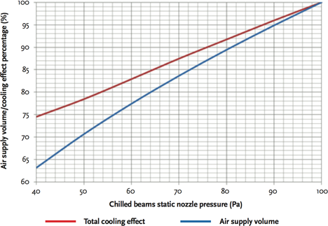
Figure 5: Relationship between the primary air static nozzle pressure to air supply volume (%) and total (airside + waterside) cooling effect (%), based on constant chilled water mass flow rate
For occupied reduced air volume conditions, it is important that the active beam is correctly selected to ensure both adequate fresh air supply and proper air distribution in the room. Recent improvements in chilled beam induction technology make it possible to reduce the supply air volume to approximately 60% of the normal design condition and still maintain appropriate diffusion. This is achieved without any need for moving parts or motorised dampers directly on the chilled beams, with a correctly designed DCV chilled beam system only requiring a single duct- mounted control damper to service a zone of multiple chilled beams.
Properly considering both the application of chilled-beam technology and options that extend the ‘normal’ can provide significant lifetime carbon savings, but it is important that the design and operation are considered along with that of the whole building and its systems.
© Tim Dwyer, 2014.
References
- CBCA Design Guide – An Introduction to Chilled Beams, Chilled beam and ceiling association, HEVAC, 2012.
- Gaskell, A.J. CBCA Technical Fact Sheet 2, EDSL TAS Energy Study Findings, CBSA June 2013.