Fume cupboards (also known as fumehoods) have a wide range of applications,from education through to research andmanufacturing. But whatever the application,the function is the same – preventing airborne contaminants inside the fume cupboard from affecting the human operator. This is achieved by maintaining the positive direction of airflow away from the operator, as well as by diluting the contaminant in the cupboard. The movement and supply of conditioned air for fume cupboards consumes significant amounts of energy – several times more than that required for a similarly-sized general laboratory.
Increasingly, the designer and operator are seeking both to realise a safe environment andminimise the environmental and financial consequences of exhausting large volumes of conditioned air. This CPD will consider the application of variable volume fume cupboards as a means of reducing operating energy cost.
The fume cupboard
The fume cupboard is fundamentally a cabinet with a sash opening (a robust, transparent panelthat traditionally slides vertically) on the front face for access, and an extract duct for removing contaminated air (Figure 1).
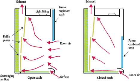
Figure 1: A variable air volume fume hood with vertical sash
Typically, the user will have their body outside the working zone and their arms and hands within the fume cupboard, manipulating vessels and materials that sit on a flat surface (often drained to a spillage tray) with a raised edge at the front. The measure of effectiveness is, in practice, quite straightforward – it is the ability of the user to operate in the fumecupboard while preventing any unwanted spill of the contents on the operator or the environment.
The successful operation of a fume cupboard is not only a result of appropriate design but also a direct result of the control and monitoring regimes. This is produced by a controlled flow of inward air, passing around the user, that is then removed through an extract system or filtered and reintroduced into the space. The actual pattern of flow is affected by disturbances from the operator, draughts from within the room and other effects, such as jets from room supply air diffusers. ASHRAE1 recommend that the velocity of any external disturbing air movement should be no morethan half – and preferably kept to less thanone third – of the design face velocity, to avoid interference with the proper operation of the cupboard. So a (fairly typical) operating face velocity of 0.5 m·s-1 could tolerate a maximum local disturbance air velocity of 0.25 m·s-1 before potentially affecting the inlet air flow regime.
The fume cupboard extract must also work to scavenge consistently across the work surface,removing the contaminant; this is frequently assisted by baffle plates at the rear of the cupboard. The design and control must be such that, whatever the disturbance, the flow of air through the cupboard entrains the contaminant and removes it at a rate that prevents it spilling significantly into the occupied zone. The cupboards will be designed to draw air as smoothly as possible through the opening. The design of the cupboard itself (Figure 2) will be a specialist task, and whatever cupboard is installed, the flow patterns within it are likely to be complex – with eddy currents and flow reversal in places – but it is the inward flow that is key to maintaining the integrity of the system. BS EN 14175 Fume cupboards provides the standards appropriate for general use fumecupboards2 but, as in this article, excludes those for specialised applications (for example, microbiological safety cabinets and those used for radioactive work). School laboratories are considered to have specific needs, and specific guidance is given in Building Bulletin 88, FumeCupboards in Schools.3
The design of any fume cupboard installation requires properly integrated practices. It is not appropriate to design the mechanical ventilation system and then apply control packages with the hope of providing the desired environmental and safety control. The functiona nd process of the system must lead the design, defining the control requirement (and eventual controls system) as well as other operational needs, including commissioning, maintenance and repair.
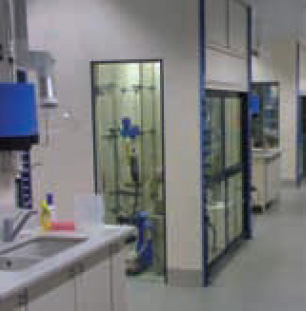
Figure 2: Example laboratory VAV fume cupboard installation
Make up air supply
The ventilation requirement to satisfy the occupants of a space in a typical laboratory is normally lower than the combined exhaust air requirement of the fume cupboards. To operate all the systems at constant volume would be inappropriate, as the demands from the fume cupboards are likely to be varying and intermittent, so it is both environmentally and financially unacceptable to run constant volume devices.
This is not only because of the fan power required, but also because any air that is drawn through the installation must be treated(heated/cooled/humidified and filtered) so that it maintains appropriate conditions in the occupied space. So, to reduce the supply volume flow rate, cupboards have been developed that use electronic controls to ensure containment while saving energy, by varying the supply flow rates to match the demand of the space and fume cupboards.
By incorporating exact positioning of the baffles in the rear of the fume cupboard and horizontal sashes with sliding windows,variable air volume (VAV) fume extract systemscan provide a far more energy-efficient method of control. The airflow rate is adjusted by measuring the face velocities across the open sash that will adjust the extract ‘valve’ (an air‘damper’ – an example is shown in Figure3) to maintain the integrity of the operating zone while allowing the face velocity across the opening to be at the required value. Such systems will typically allow set velocities of 0.35m·s-1, adjustable up to 1.0 m·s-1.
Traditionally, it was not unusual to size the constant volume supply air systems basedon a 60% operation diversity (to reduce theinstallation and operation costs). The air system was sized to supply this reduced amount to cupboards; this potentially meant that if more fume cupboards were in operation, the system may be starved of supply air. Consequently,the room static pressure could vary, causing problems with the integrity of the whole building ventilation system.
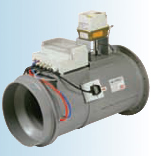
Figure 3: A VAV valve complete with integral controller
In conjunction with full variable volume supply, the extract flow rates of the active fume cupboard can be measured and added together to provide the set point for the supply air (with a small offset to keep the laboratory slightly negatively pressurised). Hence, thea irside operating costs are directly related to the number of fume cupboards operational and their sash opening position.
When all sashes are in their closed position (with the system still providing a safe minimum extract volume), there is likely to be a requirement for minimum air change rate for ventilation in the laboratory, as well as to meet the requirements of heating and cooling. In this case, a general extract damper can be opened to increase the extract flow rate so that the supply air rate will rise to meet the requirements. If, subsequently, the fume cupboards start to increase their extract rates, the general extract damper will modulate to maintain the correct room pressure (and air flow rate).
If the room temperature control requires more air to meet the heating/cooling load, the general extract shall extract more – in turn, opening the supply air further to satisfy therequirement. At all times, the relative pressures are maintained to ensure appropriate air flow through the fume cupboards.
The low cost of variable speed devices(inverters) for fan control has encouraged the widespread adoption of VAV systems for fumecupboard installations. Having been designed and installed properly, successful operation is dependent on operator discipline and the fumecupboard control system.
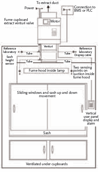
Figure 4: A VAV fume cupboard, with horizontal and vertical sashes
The schematic of the fume cupboard in Figure4, read in conjunction with the overall system in Figure 5, provides an example of how appropriate control can be applied to provide a solution. In this case, two air sampling probes are fitted inside at the top of the fume cupboard, adjacent to the light fitting, and two sampling probes are mounted on the outside top face of the cabinet.
The extract volume is measured with a venturi device built into the extract valve (damper) that provides a velocity pressure calculated to provide a volume measurement (in m3·s-1) using the venturi factor and the valve size.
The flow and, importantly, the velocity maybe obtained from the simple flow equation for sharp-edged openings as:
Q = A Cd (2ΔP·ρ-1)0.5
where Cd is a constant relating to the opening known as the coefficient of discharge ρ is the density of air ΔP is the pressure drop across the opening.
The average face velocity, vf, across the sash opening area, A, is: vf = Q·A-1 and so:vf = Cd (2ΔP·ρ-1)0.5 = Cd ΔP 0.5 (2·ρ-1)0.5 and if the air temperature in the occupied zone remains roughly constant, the density, ρ,will stay constant, so this relationship may berewritten as: vf = KCΔP0.5 where KC is a constant that can be determined by testing the cabinet and measuring the flow rates when it is being commissioned.
The probes inside the cabinet are joined together to provide an average internal pressure signal and – used in conjunction with the pressure signal from the probes outside the cabinet and a knowledge of the cabinet flow coefficient and volume flow derived from the venturi – these are transformed into a velocity signal (by the controller) that is expressed visually on the control panel, and so adjustably controlled. This provides control over the face velocity without the requirement of a sash height position measurement or a sliding window opening measurement.
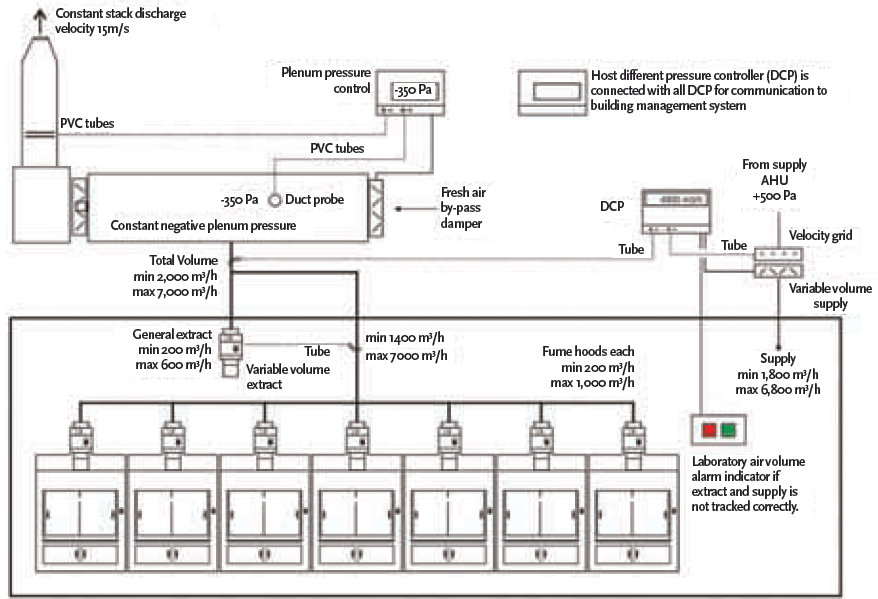
Figure 5: Example of VAV fume cupboard layout for a laboratory
In the example system (Figure 5), to ensure fast system response to changes in sash position or required face velocity, the exhaust is drawn into an extract plenum that is maintained at a constant suction pressure by a constant speed extract fan and bypass damper. For example, if the sash was opened, the pressure would decrease in the fume cupboard control system, opening the extract valve to allow more air to pass through the fume cupboard. This, in turn, would create a decrease in static pressure in the extract plenum, so the fresh air bypass would close to maintain constant suction pressure. This would all happen within a few milliseconds.
At all times, the stack discharge velocity is kept at a preset value by varying the fresh air bypass.
The changes in exhaust air flow need to be balanced by the supply into the room. In this example, all extract volumes are measured and added together to form the set point for the supply air (being monitored using a velocity grid – a fixed set of air static and velocity pressure probes) with an offset to maintain a slight negative room pressure relative to the corridor. As more supply air is required, the fan speed of the supply system is increased. If all the sashes are closed, then the supply system will be supplying the minimum requirement to ventilate the laboratory, so saving on heating, cooling, humidification and fan power.
There are requirements in BS EN 14175 for the clear, local, unambiguous indication of performance, together with appropriate alarms in the case of failure – this is integrated into the example system control panel.
Although simple in concept, the VAV fume cupboard system requires properly integrated and maintained sensing and control and, as with all proper HVAC design, should be designed holistically, taking the practical operating needs into account. The result should give a system that provides a more controllable cupboard face velocity and significant reduction in energy costs compared with a traditional constant volume system.
© Tim Dwyer, 2013.
References
- 2011 ASHRAE Handbook – HVAC Applications, Chapter 16, ASHRAE 2011
- BS EN 14175-2003 Fume cupboards.
- Building Bulletin 88, Fume Cupboards in Schools, Architects & Building Branch Department for Education and Employment, 1998