The industry that designs, manufactures, supplies and installs solar thermal heating systems was disappointed when, at the end of March, the UK government’s Department of Energy and Climate Change (DECC) announced that the Renewable Heat Incentive (RHI) funding scheme for domestic installations was not going to commence in 2012 as had previously been anticipated. Commercial systems can already attract RHI funding; however, there are also good reasons for the application of this technology to domestic properties – not least its positive lifetime carbon impact. This article will develop from the previous Solar thermal – solar hot water heating CPD published in February 2009 (available at www.cibsejournal.com).
Solar thermal adoption
In a market report1 published in 2011, the take up of solar thermal per capita in the UK was one third that of countries of similar climates, such as Ireland and Holland. Sceptics may consider that the solar resource is somehow different outside the UK but, as attested by the data in Figure 1, there is little variance in the solar irradiance between example locations at approximately the same latitude (Amsterdam, Birmingham and Limerick) or even for those in the more northerly locations (Belfast and Edinburgh).
There are strong reasons for solar thermal to be considered, even in maritime temperate climates such as the UK.
Properly sized and installed systems are responsible for almost no direct or indirect operational carbon emissions and, when combined with solar photovoltaic (PV) sourced power, the parasitic power consumption of the solar system pumps can be practically eliminated. So when predicting life cycle costs for solar thermal, the costs are independent of the vagaries of fuel prices, as well as there being a certainty of fuel security (although in operation the remainder of the domestic hot water system is unlikely to function without external power). The principal components of solar thermal systems have typically-quoted life expectancies of in excess of 20 years and, in a number of studies3,4,5 (both in the UK and in other climates), such systems have been shown to have carbon payback well within the lifetime of these components. (‘Carbon payback’ is the CO2 emissions due to system manufacture and installation, divided by the annual reduction in operational CO2 emissions when compared to a fossil-fuelled hot water heating.) Even when the sometimesoptimistic solar utilisation figures used in academic studies are replaced with the average measured data taken from the recent Energy Savings Trust monitoring6 of domestic applications, the carbon performance is still beneficially positive. And, pragmatically, the application of solar thermal hot water can help meet the thermal requirements of the building regulations as part of an holistic design process.
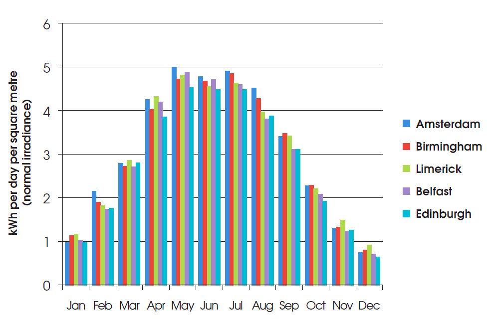
Figure 1: Average daily total normal irradiance in Amsterdam, Holland; Birmingham, UK; Limerick, Ireland; Belfast, Northern Ireland; and Edinburgh, Scotland (based on PVGIS2 data)
Maintenance requirements are relatively low, and similar to that of a small hydronic heating distribution system. However, as the heat transfer fluid in closed indirect solar thermal systems is protected from freezing by being a propylene glycol solution, there is a greater propensity for leakage compared with plain water. So fill levels need to be checked regularly and the quality of the glycol solution should be checked annually, as it can degrade at high temperatures, reducing its anti-freeze effect as well as increasing its acidity.
As from 6 April this year, planning permission is no longer required to install solar PV or solar thermal on non-domestic buildings in England – there are already permitted development rights (PDRs) for domestic installations. This recent amendment to PDRs7 in England is likely to encourage an increased number of retrofitted installations on commercial and agricultural buildings. The new rules will also mean that ground-mounted systems up to 9m2 will be able to go ahead without a planning application. There are limiting restrictions associated with the PDR that are mainly associated with the appearance of the installation.
UK government funding
The UK government has reaffirmed its support for renewable heating in domestic premises and will set out a firmer timetable for delivering this support in the autumn, with an anticipated introduction of a funding mechanism (likely to be the RHI) from summer 2013. The RHI is already in place for non-domestic applications but has only successfully registered a small number of installations to date. The level of RHI funding (now at 8.9p per kWh of metered heat output) is proving so attractive that some contractors are able to offer installation of solar thermal systems at no cost to the commercial users, by taking the RHI payments to pay for the scheme.
The Renewable Heat Premium Payment (RHPP) ’voucher scheme‘ has been available for domestic applications since the start of this month (May 2012) and provides a £300 voucher (valid for three months from issue) towards the cost of a domestic solar thermal installation when installed by a Microgeneration Certification Scheme (MCS) certified installer (eligibility is subject to the domestic premises having a specified minimum thermal performance). Although £300 may seem a relatively small amount compared to the typical domestic solar thermal cost of around £3,000 to £5,000, the assurance of having the system installed under the auspices of the MCS will ensure that the installations are eligible for support through the RHI, providing they meet the eligibility criteria of any future RHI scheme.
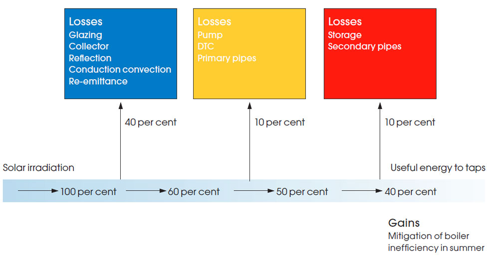
Figure 2: A representation of the indicative inefficiencies in a solar thermal system (Source: EST131, 2006)
There are ring-fenced RHPP funds available for community renewable heating systems, and for social landlords to upgrade heating systems. Again, this is likely to encourage the further application of non-domestic solar thermal systems.
The positive life time economics of solar thermal water heating are currently dependent on the provision of subsidies and would not be likely to ‘pay-back’ in real cost terms when offsetting a fossil fuelled or even an electric hot water heating system.
The ‘inefficiencies’ of operating thesolar thermal system
The performance of solar thermal is considered in different terms to that of a traditional heating resource. The energy resource itself is practically unlimited (and free), and the amount that can be utilised will be related simply to the area that is being captured and the effectiveness of transferring the heat from the incident photons of solar energy to the end use (in this case, hot water). In practical terms, Figure 2 provides an approximate breakdown of where the potential heat is lost. Many of the losses in the yellow and red boxes may be minimised by appropriately insulating the pipework, fittings and storage vessels. (In the EST 20115 survey, poor insulation of hot-water storage cylinders and pipes contributed significantly to heat loss and low performance, although it notes that this is a common issue with all waterheating systems and not just solar thermal systems.)
The typical control mechanism used by solar thermal systems, the differential temperature controller (DTC), as well as the anti-legionella protection, can have a significant effect on the efficiency of the systems, and so require properly considered design and operation. (Through novel control strategies, other than simple DTC, there are systems claiming that substantial increases of useful heat may be utilised in an annual cycle.) The energy used by the heat transfer fluid circulating pumps will be relatively small5; however, since they will be operating at all the times that the solar circuit is in use, they should be appropriately selected to operate at high pumping efficiencies at the design flowrates (the pump may, of course, be powered by solar PV).
The solar thermal system will also reduce the need for an otherwise potentially partloaded boiler in summer, hence providing a gain in overall system efficiency.
The remaining ‘inefficiencies’, as shown in the blue box of Figure 2, are related to the physics of the collector. The principal form of the collectors (as discussed in the CPD in February 20098) are ‘flat plate’ and ‘evacuated tubes’, and each has their own performance characteristics and particular attributes. However, the effectiveness of a solar collector may simply be defined by:
| Useful heat passed from the collector to the system |
| Incident radiation striking the collector’s absorber |
And this relationship has been used to develop the commonly used performance equation for solar collectors – the Hottel-Whillier-Bliss equation9,10, for when the solar irradiance is G (W/m2):
Useful heat = collector area x G x [(FR x τ x α) – (FR UL(θi – θa)/G)]
where:
τ is the transmittance of the clear cover;
α is the absorber’s shortwave absorptance;
FR is a ‘heat removal factor’ used to allow practically measurable temperatures to be used in the equation;
UL is the overall heat loss factor – this rises as the value of Δθ increases;
and (θi – θa) (or Δθ) is the specific temperature difference between the inlet heat transfer fluid and the ambient air.
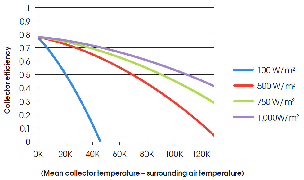
Figure 3: Efficiency of an example flat plate collector at different solar irradiances
The clear coating (typically glass or plastic) needs a high value of τ at wavelengths associated with solar radiation, as well as providing good insulation to keep UL low. The absorber surface coating needs to be ‘selective’, having a high absorbtance in the solar spectrum and a low emissivity in the thermal (infrared) spectrum. Plain metals such as copper and aluminium have low solar absorptance, and so a thin layer of a material with high solar absorptance and good infrared transmittance, such as ‘black chrome’, is applied to the metal.
In flat-plate collectors, thermal insulation is used around the casing to reduce losses.
Values of FR(τ α) and FR UL are provided using independent tests (as specified by ASHRAE Standard 93 Methods of Testing to Determine the Thermal Performance of Solar Collectors) by manufacturers as a standardised way of characterising the output of a solar collector. In Europe, BS EN 12975 Thermal solar systems and components — Solar collectors is used as the standard method for defining a collector’s performance. Although based on the same fundamental relationships, the BS EN 12975 test methods provide three values that are used to define the performance:
Collector efficiency = η0 – (a1 x (θm – θa)/G) – a2 x (θm – θa)2/G)
where:
η0 is the efficiency when the collector is at the same temperature as its surroundings (and is often referred to as the ‘optical efficiency’);
a1 and a2 are loss coefficients; and the ‘collector’ temperature is given in terms of its mean temperature, θm.
Using data from a manufacturer’s catalogue (η0 = 0.779, a1 = 1.07 , a2 = 0.0135), representations of collector performance may be produced, such as that in Figure 3.
The characteristics of collectors can vary widely and deserve appropriate attention (with the same rigour as any other piece of HVAC equipment) when being selected.
Properly designed solar thermal systems are a means of capturing the sun’s energy for use in buildings that, until the cost drops or efficiency rises for photovoltaic technology, can provide a most carbon-effective method of generating hot water. To make them most cost effective requires careful selection, design and operation but, unfortunately, without subsidy they are unlikely to break even financially.
© Tim Dwyer 2012
Further reading:
Solar water heating systems – guidance for professionals, conventional indirect models (CE131) provides a good overview of the technologies and is freely downloadable from the Energy Savings Trust: www.energysavingtrust.org.uk
The CIBSE Solar heating design and installation guide provides some detailed description on systems and appropriate installation details, and the CIBSE
Capturing Solar Energy (KS15) (freely downloadable to CIBSE members from www.cibseknowledgeportal.co.uk) gives an accessible and succinct introduction to a number of solar technologies, including solar thermal.
BS EN 12975 and ASHRAE 93 provide extensive detail of the testing requirements for solar thermal collectors.
The US-based Solar Rating and Certification Corporation – www.solar-rating.org – provides data for numerous tested collectors.
References
- Solar Thermal Markets in Europe Trends and Market Statistics 2010 – European Solar Thermal Industry Federation, June 2011.
- Photovoltaic Geographical Information System (PVGIS) – http://re.jrc.ec.europa.eu/pvgis/
- Croxford, B. and Scott, K., Can PV or Solar Thermal be cost effective ways of reducing CO2 emissions for residential buildings? Solar 2006: Renewable Energy – Key to Climate Recovery. American Solar Energy Society: Denver, USA.
- Beccali, G. et al, Life cycle assessment of a solar thermal collector. Ardente, F. Renewable Energy 30 (2005) 1031–1054.
- Streicher, E. et al, Energy Payback Time – A Key Number for the Assessment of Thermal Solar Systems, EuroSun 2004.
- Here comes the sun: a field trial of solar water heating systems, Energy Savings Trust 2011.
- The Town and Country Planning (General Permitted Development) (Amendment) (England) Order 2012 – www.legislation.gov.uk/uksi/2012/748/made
- Dwyer, T., Solar thermal – solar hot water heating, CIBSE Journal, February 2009 – www.cibsejournal.com/cpd/2009-02/
- Hottel, H.C. and Whillier, A., Transactions of the Conference on the Use of Solar Energy, vol.2, part 1, Univ. of Arizona Press, 1958.
- Bliss, R.W., Solar Energy 3, 1959.