This CPD article will cover some of the issues surrounding the design and selection of commercial solar thermal solutions.

Using solar energy to heat water has been commercially available in the UK in a variety of forms since the mid 1970s. The UK can offer a good climate for solar thermal solutions, benefiting from around 60% of the solar energy received at the equator, and the UK is comparable with the European countries better known for their solar applications (see Figure 1).
Figure 1: Monthly solar irradiance on a flat plane facing south with a tilt angle of 45° for Athens, Birmingham and Zurich (Data from BS EN 15316-4-3:2007 Part 4-3: Heat generation systems, thermal solar systems)
In the UK the average annual available solar irradiation varies between around 1,200 kWh/m² on the south coast of England and up to 900 kWh/m² in Scotland – only 55% of the sun’s light is visible, the balance being ultraviolet and infra-red, and only around 25% of the sunlight is direct, with the remainder being diffuse. A properly designed and installed solar thermal system can maximise the capture of this power and translate 60% of it into useful energy for hot water systems.
Roof-mounted solar collectors with high transmission and absorption efficiencies typically capture energy from incident solar irradiation, passing the heat into a transfer fluid – usually a pre-prepared mixture of 60% water and 40% glycol to prevent freezing during periods of low outdoor air temperatures. Different specifications of heat transfer fluid are available for different types of solar collectors. The heat transfer fluid is usually pumped through a coil located in the lower section of an unvented indirect cylinder and, in so doing, heats the stored water that would normally be used for domestic hot water.
A well-designed commercial solar thermal system may be able to satisfy around 30 to 40% of the annual hot water load, known as the solar fraction (SF). To try and achieve a higher solar fraction may lead to solar thermal system operational issues. In the summer months, an appropriately designed solar thermal system should be able to satisfy almost all of the hot water demand in many cases.
The SF is much lower during the colder winter months, when the available solar irradiation is a lot lower, resulting in SF levels of around 20%. To increase the annual average SF in the winter months, a larger number of solar collectors would be needed – but the array would be oversized for the summer period and this could lead to stagnation resulting in possible long-term, irreparable damage to the solar collectors.
Principal types of solar collector
There are two main types of solar thermal collectors currently being used in the UK commercial building services sector. These are glazed flat plate and evacuated tube collectors.
The typical construction of a glazed flat plate collector comprises a lightweight aluminium tray or frame, which contains a layer of insulation to prevent heat loss via conduction through the rear of the collector. A series of copper pipes is laid in a ‘harp’ or ‘serpentine’ arrangement within the insulation, to carry the heat transfer fluid through the collector. A very thin copper absorber is ultrasonically welded to the copper pipes. The absorber has a selective coating in order to maximise solar irradiation absorption.
Finally, the collector has a transparent glass cover with a low thermal expansion coefficient such as borosilicate glass (Pyrex), and high transmission efficiency to minimise convection losses.
Transmission efficiencies for good-quality products are more than 90%, absorption efficiencies 95%, emissions (losses) five per cent, and maximum thermal efficiencies around 78%. An installation of flat plate collectors is shown in Figure 2.
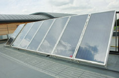
Figure 2: Application of roof-mounted flat plate solar collectors – each panel has a 2.55² gross area, 2.21² absorber surface area, 90.8% transmission efficiency and 95% absorption efficiency
The construction of an evacuated tube collector is entirely different from that of a glazed flat plate collector, although materials used are common to both types – copper tubes to carry the heat transfer fluid, a copper absorber with a selective coating, and tubes manufactured from glass with a low thermal expansion coefficient.
Evacuated tube collectors generally comprise a manifold and a series of glass tubes (20 or 30) connected in parallel. A vacuum is created within each tube during the manufacturing process; this effectively acts as an insulator for the absorber and reduces convection losses, particularly during colder winter periods. While transmission efficiencies, absorption efficiencies and emissions are comparable to those offered by glazed flat plate collectors, the thermal efficiency is higher as a result of the presence of the vacuum, with values of around 83%. An installation of evacuated tubes collectors is shown in Figure 3.
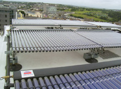
Figure 3: Evacuated tube solar collectors installed on a mixed-use university building on the south coast. The gross area of each collector (each with 30 tubes) is 4.25² (3² absorber surface area). This collector array heats an indirect solar cylinder with capacity of 1,500 litres used to pre-heat water for two direct-fired water heaters
Whether glazed flat plate or evacuated tube collectors are used, the optimum angle of orientation is south facing and the optimum angle of inclination between 30 and 45 degrees from the horizontal. Direct flow evacuated tube collectors, where the heat transfer fluid is pumped through each tube effectively connected in parallel, offer greater flexibility with regard to the positioning of the collector array. These collectors can be placed flat on the roof or vertically on a façade, giving the ability to rotate each tube to optimise orientation and inclination by about +/- 25 degrees. So, even if the location is not directly facing due south, the tubes can be adjusted accordingly to maximise solar energy absorbtion.
Indirect solar cylinders
Frequently in winter the balance of energy required to satisfy the demand is supplied by the primary heating appliance – a heating boiler or direct-fired water heater. During the summer period, the solar energy absorbed by the collectors and transferred into the hot water can negate the need for any energy at all being provided by the primary heating appliance – this can have a significant impact on reducing carbon dioxide emissions and reducing energy bills.
For example, consider the system in Figure 4, a direct-fired water heater system to raise the incoming cold water supply at 10°C to a legionella-safe water temperature of 60°C (ie a separate boiler is being used for the space heating). A pre-heat cylinder served by an array of roof-mounted solar collectors can be used to supply pre-heated feed water to the directfired storage water heater, so requiring less fuel to raise the water to the required set point of 60°C.
Figure 4: Schematic of an example solar thermal system integrated with a direct gas-fired water heater
In the summer months there may be sufficient solar irradiation over prolonged periods of the day, such that the water in the preheat cylinder is able to reach temperatures in the region of 75°C to 80°C. In such circumstances, depending on how the pre-heat cylinder and collector array have been selected, the solar energy could be sufficient to supply the required water temperature at the outlets. At these water outlet temperatures it would be necessary to install a thermostatic mixing valve between the hot outlet of the pre-heat cylinder and the storage water heater, unless there are point-of-use mixing valves used within the building.
Another example is where commercial boilers are being used for space heating and the generation of hot water via an indirect calorifier. For boiler applications, the main principle of generating the solar thermal energy and the use of an indirect cylinder are the same as for direct-fired water heaters.
The difference is in the design of the cylinder, in that it frequently would have two indirect coils (although some systems do use a separate pre-heat cylinder) as in Figure 5.
At times when there is insufficient solar energy to heat the water to the set point (eg 60°C) the commercial boilers would provide the additional energy required to raise the water temperature to the required set-point.
Figure 5: domestic hot water cylinder with two indirect coils (Solar heating design and installation guide, CIBSE 2007)
The control of the transfer of energy from the collector array and the indirect cylinder is conducted in the same manner, whether the primary heating appliance is a direct-fired water heater or a commercial boiler. There is a differential temperature control via a sensor at the outlet of the solar collector array and a sensor located in the lower portion of the cylinder. When the temperature differential is greater than, typically, 7K the control unit switches on the pump, allowing the energy captured within the solar collectors to be circulated and transferred into the water via the indirect cylinder coil. When the temperature differential is typically less than 3K, the pump is switched off.
For commercial applications, the issue of development of legionella bacteria in the solar cylinder is often the subject of much concern as the water could be stored at temperatures at which the bacteria can develop (20°C to around 45°C favour growth). This can be overcome with appropriate design and properly informed operation. For example, cylinder pasteurisation can be conducted through the use of shunt connection between the storage water heater and the pre-heat cylinder and, for twin coil cylinders, a destratification pump can be used.
Cylinder selection and design
There are a number of issues to consider when selecting the capacity of the solar cylinder and the design of the indirect coil. The issues apply to both direct-fired water heater and commercial boiler applications.
In order to maximise the SF, the capacity of the solar cylinder should be matched to the daily hot water demand. In so doing, during the summer months when the available solar irradiation is at a maximum, it may be possible to satisfy the whole hot water load, depending on the demand profile of the property. This could entirely offset the need to burn fossil fuel in the primary appliance to generate hot water.
For glazed flat plate collectors, the rule-of-thumb measure is 50 litres of stored water per m² of solar collector array (the active area rather than the gross physical area). Evacuated tubes are more efficient than glazed flat plates, particularly during the colder winter months, as this type of solar collector is less prone to heat loss via convection. For a given surface area the evacuated tube collectors can hold more than twice as much heat transfer fluid. As a consequence, the rule of thumb on sizing and selection is 70 litres of stored water per m².
This ratio between collector array surface area and the volume of stored water is one of the key factors in delivering the optimum SF but, at the same time, ensuring the collectors do not enter into frequent and prolonged periods of stagnation. Even if the correct volume of storage is selected for a given solar collector array, there is still the need to be able to discharge this useful energy into the water stored within the indirect cylinder. The relationship between the surface area of the indirect coil and the absorber surface area of the collector array is critical with regard to dissipation of the solar energy into the water. Very much like a burner, heat exchanger and water flow through a boiler, the solar collector array is the heat generator. If the heat is not discharged into the water, then the heat transfer fluid will return to the collector array and this will affect collector performance and could result in collector stagnation.
Conclusion
The application of solar thermal systems employs traditional skills with readily available technology. On new-build projects there is activity on the roof of the building, during which the solar collectors may be installed. Beyond the collectors, and in the plant room, the work is predominantly hydraulic and can be carried out by the mechanical contractor installing the remainder of the equipment. The presence of the solar collectors on the roof also offers a visible indication that the enduser has taken positive action and invested in a technology that reduces the carbon footprint of the building.
Solar thermal solutions offer an opportunity to significantly reduce carbon dioxide emissions – approximately 100 kg CO2/m² of collector array per annum when compared with a natural gas primary heating appliance (based on a gross thermal efficiency of 80% with gas 0.193 kg CO2/kWh) – contributing to the renewable energy commitment required by local authorities and the increased requirement to include LZC technologies. The impact is particularly marked as domestic hot water becomes an increasingly dominant load as building air tightness and insulation levels improve and space heating loads reduce.
© Compiled by Yan Evans, technical director at Baxi Commercial Division, and Professor Tim Dwyer, London South Bank University