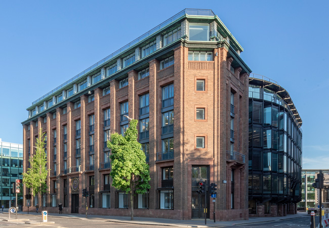
Bracken House Credit: Arup
Bracken House in the City of London is an unusual blend of tradition and modernity. Originally designed by Sir Albert Richardson, the building started life in the late 1950s as a purpose-built home for the Financial Times newspaper – the pink sandstone of the building’s classical-style façades is said to have been selected in homage to the paper’s distinctive pink pages. Back then, Richardson’s scheme featured two classical-style wings for offices which bookended the building’s industrial heart housing the paper’s giant printing presses.
When the FT moved out in 1989, the building’s new owners, Obayashi Corporation, hired Hopkins Architects to transform the building into a contemporary office environment. Its listing in 1987 prevented the building from being demolished. Hopkins’ solution was a scheme that retained the building’s classical wings, north and south, but replaced its more utilitarian central element with a corrugated, high-tech steel- and glass-fronted office building (which was subsequently listed in 2013). The scheme included a building services solution designed by Arup for the building’s then tenant – an Asian bank.
In 2014, when the bank vacated the premises, Obayashi Corporation turned to John Robertson Architects (JRA) to modernise sympathetically the 26,000m2, five-storey building (plus its three levels of basement), bringing it up to contemporary office standards. At the same time, Arup was asked to devise an efficient building services scheme compatible with the building’s latest reincarnation three decades after the consultant’s initial involvement.
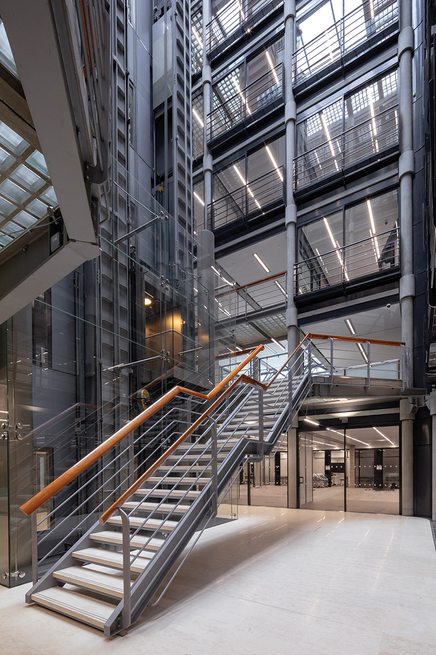
JRA’s architectural enhancements included: replacing sections of the Hopkins-designed central atrium’s translucent glass-brick roof to let in more light; the creation of a new roof terrace, including the addition of a running track, to allow the building’s occupants to enjoy views of St Paul’s while improving their wellbeing; and the addition of two new light-wells at the junctions of Hopkins’ high-tech central block with Richardson’s classical wings to help improve connection and circulation between the different elements.
Arup’s role was to design a shell-and-core/Category A building services solution to complement JRA’s enhancements. The consultant’s brief was to increase the occupation density from a generous one person per 10m2 to one person per 8m2 for most of the floors. However, for two of the floors, which had been slated as potential ‘financial’ trading floors, the brief called for a design density of one person per 6m2.
‘Our brief was to put more people in the building than had originally been allowed for and also to enable it to be split into multiple tenancies,’ says Steven Berry, associate director, building engineering at Arup, the scheme’s building services designer.
Arup’s original 1990s building services solution had kept the bank’s employees comfortable using a variable air volume (VAV) system. This supplied treated air to a floor plenum where it mixed with recirculated air before reaching the occupied space through circular diffusers, via fan air terminal units.
Exhaust air was extracted at high level through outlets in the shallow ceiling void, which connected to an exhaust duct running in the plenum of the floor above.
To help deal with the increased heating and cooling loads in areas near to the façades, the VAV system was supplemented with fan coil units (FCUs) in the floor plenum. A minimum fresh air system supplied treated fresh air to this perimeter zone. The same FCU/minimum fresh air system was used to maintain comfort in the building’s two wings.
The system was served by heating and cooling plant located in the building’s lower basement plantroom in addition to the air handling units, chillers, tanks and pumps. The only major item of plant not to be housed in the basement was the heat rejection plant for the water-cooled chillers that were located in a ‘well’ on the roof. The primary pipework and ductwork distribution was also in the basement with risers delivering the services vertically to the floors above.
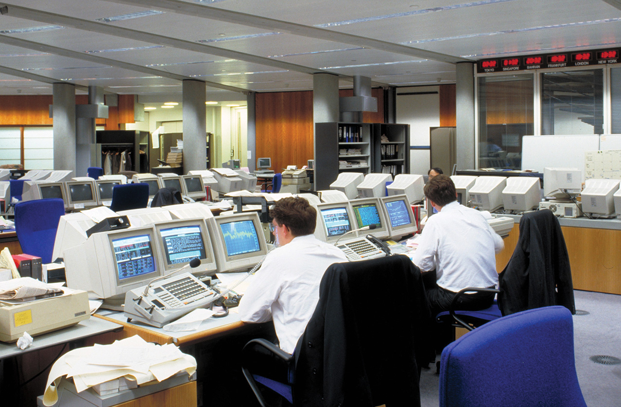
Heating loads from IT equipment were high in the 1990s. Credit: Arup
Under the refurbishment, all the existing plant was stripped out. However, the plantroom and distribution risers were retained for use in Arup’s new scheme. ‘The existing building services were installed in the early 1990s and had reached the end of their economic design life, many items were obsolete and were no longer supported by their manufacturers,’ explains Berry.
While Arup’s original scheme had been developed in the 2D environment, it was a client requirement that the new scheme was developed in a 3D CAD environment to generate a building information model for use by Obayashi’s FM team for asset management and maintenance. The starting point for the digital model was a cloud-point survey, initially undertaken when the tenant was still in place, to enable the design team to start developing the refurbishment solution.’
‘The ceilings were still in place and structure covered up and there were even pictures hanging on the walls,’ says Berry.
Although limited as-built drawings existed, these were not always a true reflection of site conditions so extensive surveying was required during the strip-out process. A second, more detailed cloud-point survey was undertaken after the building had been handed over to the main contractor and the raised floor and suspended ceiling removed.
Project team
Client: Obayashi Corporation
Architect: John Robertson Architects (JRA)
MEP engineer: Arup
Structural engineer: Arup
Project manager and cost consultant: Turner and Townsend
Main contractor: McLaren
MEP contractor: Skanska
‘This survey gave us some of those ‘discovery moments’. We found upstand beams where we were not expecting them, which meant we had to rejig the design, moving pipework and ductwork because we actually had less floor void than we initially thought,’ Berry says.
The building imposed a number of constraints when it came to selecting a replacement HVAC system for the refurbishment, including the requirement to maintain the current 2.7m floor-to-ceiling height. Other constraints included: a 175mm-deep ceiling void, which is unsuitable for services (except sprinklers and lighting) because it is interrupted by downstand beams; while in the 550mm-deep floor plenum, upstand beams impose a limit on the height of the services that can be distributed within the void and restrict service crossovers to the areas between beams.
Credit: Arup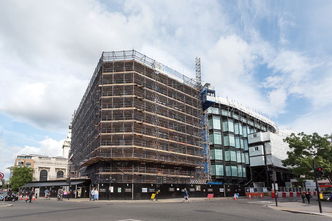
A number of HVAC systems were reviewed as replacement options including: underfloor FCUs; underfloor VAV units; an enhanced VAV solution, with an increased number of VAV boxes; and a passive chilled beam system with an underfloor fresh air supply. ‘We looked at a number of different ventilation options to evaluate what was feasible,’ Berry says.
Each of the four options was assessed based on its cooling performance, flexibility to accommodate changes to office layout, ease of maintainability and its ability to integrate within the building. The chilled beam solution was rejected because it would compromise the 2.7m floor-to-ceiling height. Underfloor FCUs were rejected on the basis that changing the units’ filters was considered too disruptive to tenants and because the high density of units required and their associated ductwork would be expensive and require a great deal of coordination.
Of the two VAV options – underfloor and the enhanced underfloor – the more basic solution was least expensive and required the fewest number of services in the floor void, simplifying coordination. This solution, however, lacked the level of zonal control offered by the enhanced VAV option. ‘Although the main drawback of the underfloor VAV solution is the lack of zonal control, underfloor supply systems are, to an extent, self-regulating and the level of cooling provided to the floor will naturally adjust according to where the highest loads are concentrated,’ Berry says.
Credit: Arup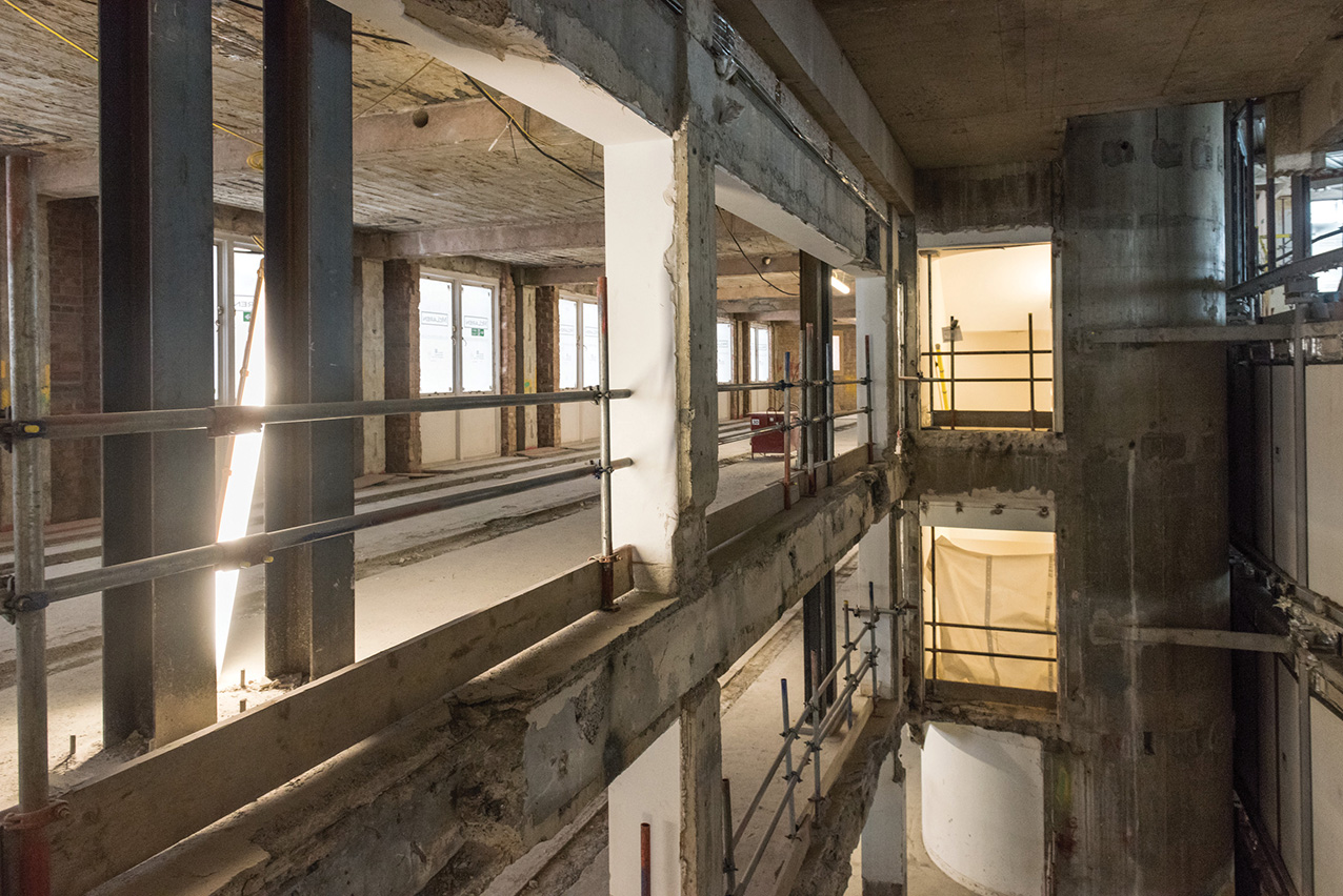
In the end, it was decided to go with the underfloor VAV option coupled with underfloor perimeter FCUs for the central building and a ceiling mounted FCU system for the building’s two wings – replicating almost exactly Arup’s original scheme from three decades earlier. ‘Ultimately, in terms of design criteria and cost, we came back to what was installed originally, which we’ve made better,’ explains Berry. He says because the FCUs are located at the building’s perimeter it is ‘unlikely that maintenance access will be blocked by furniture’.
Under this revamp, the building’s floors are designed to be occupied more intensively. ‘More people mean the ventilation loads go up and the cooling loads too,’ says Berry. In addition, the system had to have sufficient cooling capacity to accommodate the higher heat gains on the potential trading floors.
Arup’s scheme included four new, more efficient, water-cooled chillers installed in the basement. These provide a cooling capacity of 835kW per chiller, adding a total of 340kW of additional cooling capacity over the 1990s system while using the same-sized cooling towers. ‘We could get chillers that are more efficient and with a bigger cooling output, but the one criteria we could not change was the cooling tower capacity to get rid of the heat, because we could not put any more plant on the building’s roof,’ says Berry (see panel ‘Corridor of uncertainty’).
Corridor of uncertainty
Unfortunately for Arup, Bracken House is located within a strategic viewing corridor of St Paul’s Cathedral. This imposed a maximum height on the building. In the original scheme, the rooftop cooling towers were recessed into the building’s roof to keep them below the height limit. Under Arup’s new scheme, this onerous height restriction meant the engineer’s only option was to site the replacement cooling towers in the same recess.
Size restrictions meant the new cooling towers were almost a like-for-like replacement for the old. Their output means that, although they can supply the base scheme population density and the enhanced occupancy on two floors, redundancy and spare cooling capacity available for a data hall were reduced. ‘Although the cooling towers have been replaced, space constraints mean the replacement towers do not provide any significant increase in cooling capacity, which was one of the constraints we had to work within,’ explains Berry.
Space was also an issue from a building services perspective with the introduction of the two new lightwells at the junctions between the old and new parts of the building to improve connectivity between the two elements. These internal courtyards, complete with open-tread staircases and landings, also addressed the multitude of different levels between the central block and the wings.
‘To create the courtyards, we had to reposition several risers and the toilets had to be moved,’ Berry says. However, advances in technology meant that the designers were able to free up floorspace formerly occupied by the giant IT risers of the previous banking tenant.
The building incorporates a number of different lifts, including scenic lifts in the atrium; goods/firefighting lifts; vehicle and cyclists’ lifts; and a roof access lift. The scenic lifts in the atrium, which has significant historical attributes and formed part of the listing, were carefully modernised and upgraded. The goods/firefighting lifts and one of the vehicle lifts were replaced with modern alternatives. The other vehicle lift was replaced to enable cyclists to access the basement cycle store.
In a neat twist, just as the project was nearing completion and Arup’s new version of the original underfloor VAV system was being installed three decades after the original, so the FT announced that it would be taking the lease on the refurbished building, returning to its former home three decades after it had originally vacated Bracken House.
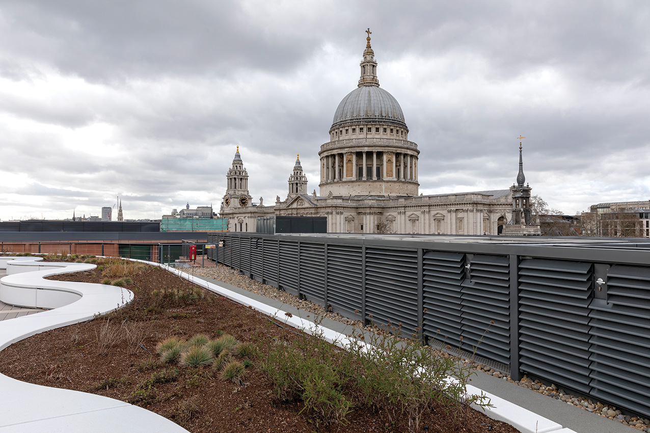
Occupants enjoy the views of St Paul’s. Credit: Arup