
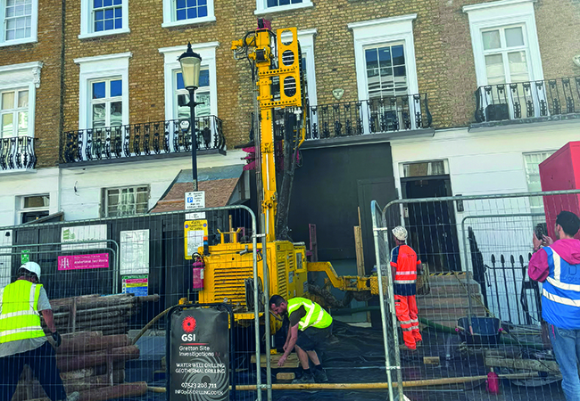
Two boreholes were drilled in the curtilage of the terraced home
How do you introduce cooling into a Grade II-listed property without compromising its historic character? That was the challenge facing engineer mstep, working alongside architect Cagni Williams Associates, on the upgrade of a 200m², four-storey (plus basement) 18th-century townhouse in London’s affluent Chelsea area.
Originally heated by a gas boiler and radiators, but without cooling, the home’s new owners wanted it to be warm in winter and ‘cool’ in summer, says Aleksandra (Sasha) Krstanovic, founder of mstep.
Project team
Architect: Cagni Williams Associates
MEP consultants: mstep
GSHP specialist:Genius Energy
LabMain contractor: Dominik
Renewables installer: Elite Renewables
Drilling contractor: GSI Drilling
Cooling will be an increasing consideration for the UK’s existing homes, with summer mean temperatures in London expected to rise by 3-5K by the 2080s, according to climate-projected weather files (CIBSE, 2025; Met Office, 2018). mstep proposed a ground source heat pump (GSHP) to supply both low carbon heating and cooling. ‘If we’re introducing a heat pump to provide cooling, we can also provide heating, which would enable us to get rid of the gas boiler,’ Krstanovic explains.
The architect convinced the homeowner of the benefits of the low carbon solution. ‘We’ve worked with Cagni Williams for many years and they explained to the client that, if they wanted cooling, then they were going to have to involve a heat pump,’ says Krstanovic, who adds that a ground source heat pump was better suited to the building than an air source one.
‘An air source heat pump would have to be located in the back garden, so it would be visible and the fan noise would, potentially, affect neighbours in this densely populated area.’
By contrast, a GSHP could be concealed in the property’s basement coal vault, in the space previously occupied by the gas boiler.
The building’s listed status restricted opportunities for fabric thermal improvements. Much of the envelope had been upgraded during an earlier refurbishment, although single glazing remained. The team did, however, take the opportunity to enhance insulation in the loft.
To establish the peak heating and cooling loads, mstep used dynamic thermal modelling. Summer design conditions were 32°C dry-bulb and 20°C wet-bulb, with an internal design temperature of 22°C in cooled rooms. Winter calculations used an external temperature of -4°C and an internal design temperature of 23°C.
A 22kW, single-phase, Volta GSHP was selected for the project, to supply peak heating and cooling loads of 18kW and 13kW respectively. A major challenge was finding space to install the ground array.
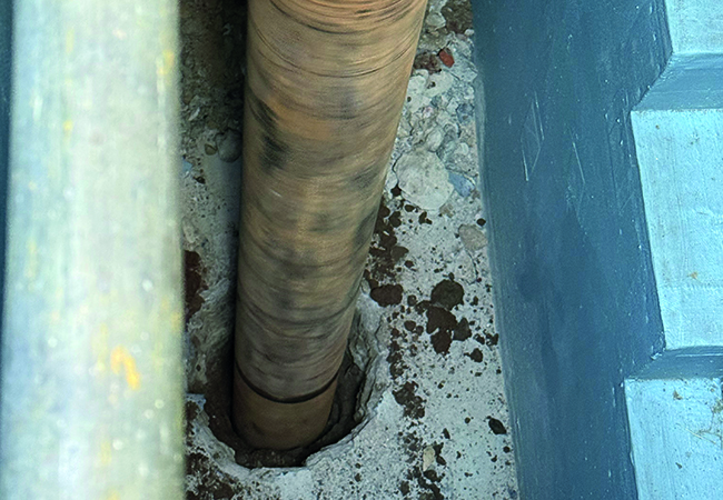
The borehole next to the property’s front steps
GSHP specialist Genius Energy Lab (Gel) undertook a geological desk study, based on British Geological Survey records, to establish the feasibility of a closed-loop system. The assessment indicated that the required heat exchange could be achieved using a single borehole approximately 305m deep, or two boreholes of around 167m, spaced 6m apart. Gel and Cagni Williams Associates have carried out a similar exercise as part of the feasibility study for a much larger ground source heat network in the same area of London (see panel, ‘Engineering heat beneath Chelsea’).
The team opted for the twin-borehole solution, with the boreholes positioned within the narrow front lightwell, immediately outside the basement entrance. This location allowed the drilling rig access from the street while keeping the installation within the property’s curtilage.
Drilling was undertaken by GSI Drilling for Elite Renewables, in collaboration with main contractor Dominik, with spoil discharged directly into a skip positioned on the street. The geology was challenging. One borehole was angled approximately six degrees from vertical to ensure adequate separation at depth, without impinging on the exclusion zone for the Piccadilly line tunnel.
Ground conditions introduced a further complication. The first borehole reached 159m before unstable fine sand in the Thanet Sands formation began collapsing into the hole. The team compensated by increasing the depth of the second borehole. The completed ground arrays connect to the adjacent GSHP.
Heating and hot water
The GSHP supplies heat to the radiators at a design temperature of 55°C flow, 45°C return.
Part of the existing heating system, the radiators and underfloor heating have been reused. mstep checked the output of each existing radiator at 55/45°C against the calculated room heat loss. New cast-iron column radiators, selected to complement the interior design of the house, were introduced where outputs fell short. Underfloor heating, operating at around 35°C, supplements the radiators in some of the rooms.
The GSHP also heats domestic hot water, which is stored in a new 300-litre horizontal cylinder. A 150-litre buffer vessel sits in the external vault. The cylinder is charged when space-heating and cooling demand is low, and takes priority over space heating when it needs recharging. The system also incorporates a pasteurisation schedule and is supported by electric immersion heaters.
Designing for summer comfort
Cooling is all-air. Two ventilation units incorporate chilled-water coils connected to the GSHP. Instead of installing conventional room air conditioning units, the design delivers air via slot diffusers concealed in the ceilings. These are selected to limit noise to 25dB(A), supporting design criteria of NR25 in bedrooms and NR30 in living areas. ‘Cagni Williams are very meticulous about details, so there was never going to be fan coils integrated into bulkheads,’ says Krstanovic.
Air to the basement and ground-floor rooms is from a Swegon supply-only unit, rated at 540L.s–¹ and hidden in the external coal vault. This incorporates a 5.43kW in-duct cooling coil. Fresh air enters the vault through a louvred door and exits the unit through ductwork beneath the basement floor before entering a plenum. From here, the air rises to high level through ductwork built into the walls.
There was insufficient space to squeeze in a return duct, so air either finds its way upstairs or exits through one-way louvres at basement and ground-floor levels. These are fitted with backdraft dampers and are concealed behind heritage cast-iron grilles. ‘We’re supplying air and letting it find its own way out or back to the unit at the top of the building, depending on how the house is working at that point in time,’ explains Krstanovic.
Replacing the gas system with the GSHP could reduce annual emissions by 4.7 tonnes of CO2
The upper floors are served by an M&Y heat-recovery ventilation unit squeezed into the loft. This delivers 260L.s–¹ and incorporates a 4.9kW cooling coil. Outdoor air intake and exhaust terminals are positioned at roof level, at least 1.5m apart. This unit supplies the bedrooms and extracts air from bathrooms one and two and the third-floor stair.
Integrating ductwork into the historic townhouse demanded close cooperation between the engineers and architects. Air is distributed via insulated rectangular plastic ducts, measuring 220mm x 90mm, where space allowed, mostly in ceilings and bespoke plenum ducts in the walls, each handling up to 90L.s–¹.
Rather than expose the ductwork or introduce visually intrusive bulkheads, Cagni Williams routed the ductwork and bespoke plenums through walls, floor voids and cupboards, so no ductwork is visible. ‘We gave the architect the duct dimensions and told them where we need to get it from and to, and the architects, who are much more conversant with the building fabric, found a route,’ says Krstanovic. However, accommodating this solution involved the removal of some walls and then rebuilding them around the ducts.
In heating mode, the radiators and underfloor heating provide space heating, with the tempered air supply rate kept to a minimum based on CO₂ levels.
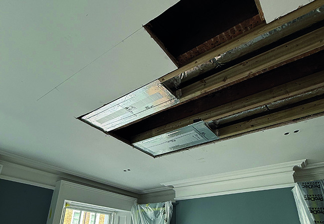
Integrating ductwork into the historic townhouse demanded close cooperation between the engineers and architects
For Krstanovic, this close integration of architecture and engineering was fundamental to the success of the retrofit. ‘Establishing the services routes collaboratively allowed the mechanical systems to be incorporated without compromising the character of the interiors.’
She describes the control strategy as ‘not particularly sophisticated’. The heat pump’s integral controls switch between heating and cooling based on the outside temperature, and heat the hot-water cylinder when required. Room thermostats are wired in parallel, so the heat pump will continue to run if any room has not reached its set temperature. ‘The system will continue to work until that space is satisfied.’
Radiators are controlled locally by thermostatic radiator valves and the underfloor heating by its own controls. In cooling mode, any cooling demand boosts the ventilation units. Similarly, CO₂ sensors will trigger an increase in fan speed and so increase the supply of outside air.
A model for historic buildings?
At feasibility stage, Gel estimated that replacing the gas system with the GSHP could reduce the building’s annual emissions by approximately 4.7 tonnes of CO₂. Krstanovic says replacing a gas boiler with ground source heating typically saves 70% to 80% on carbon dioxide emissions and approximately 50% on running costs, although energy used in providing cooling will reduce the saving.
The ground-source installation represents a substantial investment, with the heat pump and boreholes alone estimated originally at £76,000 to £90,000, excluding changes to the distribution within the house. The boreholes were ultimately delivered at a lower cost, and the project demonstrates how the constraints of a listed building can inform, rather than prevent, the development of a low carbon heating and cooling solution.
Engineering heat beneath Chelsea
The proposed Sydney Street Heat Network in Chelsea is designed around an ambient-temperature loop running beneath the public highway. It is intended to serve around 300 homes, two hospitals, a school, a church and commercial premises.
A government-funded feasibility study calculated a peak heating demand of 1,743kW and found the local geology suitable for ground-source systems, with no geological or hydrogeological barriers identified at the required drilling depths.
The proposed borehole field is the key piece of infrastructure. Genius Energy Lab developed a layout accommodating up to 174 vertical boreholes at 10m centres beneath the streets.
In such a congested urban environment, however, finding space underground is as important as the thermal design. Ground-penetrating radar was used to map existing gas, water and electricity services so that the borehole positions could be coordinated around them.
Unlike a conventional high-temperature district heating system, the ambient loop does not distribute heat at a temperature ready for use. Instead, water circulates at close-to-ground temperature, reducing distribution heat losses, while heat pumps within individual properties provide heating and cooling locally.
Locating the shared ground array beneath the highway also avoids the need for external air source heat pump units – an important consideration in a conservation area streetscape.
The feasibility work suggests the system could initially serve about 75% of local dwellings. The buried ground-loop infrastructure is expected to have a service life exceeding 100 years, providing a long-lived energy asset to which properties can connect progressively.
Planning permission has now been granted, moving Sydney Street beyond feasibility towards delivery. If realised, it could provide a replicable engineering model for bringing shared ground-source energy to existing, space-constrained urban neighbourhoods.
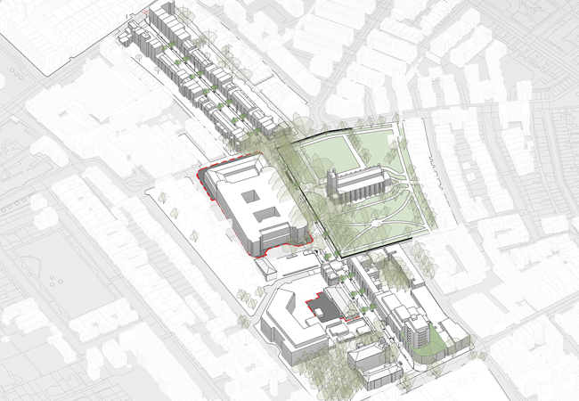
Map of Sydney Street heat network
References:
1 CIBSE. (2025). CIBSE Weather Data: UKCP18-derived Design Summer Years (DSY) and Test Reference Years (TRY). CIBSE, London.