
Sponsors: Pipe Centre
For an alternative way to access this module, CIBSE member, Jos Brownlie provides a video reading the module: Module 268 recording
Pipework insulation is often regarded as a solved problem. Select the insulation thickness, comply with recognised insulation standards, such as BS 54221, together with local building regulations, and move on to the next design decision. That assumption is becoming increasingly outdated.
For many years, pipe insulation was specified primarily to limit winter heat losses, prevent freezing and satisfy regulatory requirements. However, the context has changed dramatically. Modern buildings require far less space heating than they did only two decades ago, are considerably more airtight, and increasingly rely on communal heating systems and heat networks that operate continuously throughout the year.
At the same time, concerns about overheating have become a major design consideration. While solar gains and glazing are usually considered first, another source of unwanted heat often remains hidden above suspended ceilings, within service risers and inside communal corridors, in the form of distribution pipework. As buildings become better at retaining heat, designers must consider not only where heat is needed, but also where it is unintentionally released.
This article examines why pipe insulation is no longer simply a compliance exercise, but an important contributor to operational energy performance, thermal comfort and building resilience.
Growing importance of pipework heat loss
Looking back 20 years, the thermal performance of the building envelope dominated annual heating energy consumption. Buildings lost heat readily, insulation standards were relatively modest and heating systems generally operated only when space heating was required. Against this background, heat emitted from service pipework represented only a small proportion of the building’s energy balance.
Successive revisions to national energy-efficiency regulations – exemplified in England by Part L of the Building Regulations – alongside improvements in insulation, airtightness and glazing performance, have significantly reduced heating demand in domestic and non-domestic buildings. At the same time, communal heating systems, district heat networks (district energy systems) and centralised domestic hot water (DHW) generation have become increasingly common. Unlike space-heating circuits, DHW circulation often operates continuously throughout the year.
The absolute heat loss from a metre of insulated pipe may be little different from 20 years ago, but the amount of useful heat required by the building has reduced dramatically. Figure 1 provides a simplified conceptual illustration of how distribution losses become proportionally more significant as building heating demand is reduced.
These changes also affect occupant comfort. Heat released from continuously operating pipework is no longer easily dissipated through building fabric. Instead, it accumulates within corridors, risers, ceiling voids and service cupboards, contributing to unwanted summertime heat gains.
Pipework as a continuous heat emitter
Every heated pipe continuously transfers energy to its surroundings. Unless that heat is required within the occupied space, it represents avoidable energy consumption that has first been generated, distributed and paid for. Whether carrying DHW, low-temperature heating water or a district heating supply, heat flows from the fluid through the pipe wall and insulation before being dissipated to the surrounding environment.
This transfer occurs through three mechanisms: conduction through the insulation; convection from the insulation surface to the surrounding air; and thermal radiation to adjacent surfaces. Together, these determine the overall heat loss. Unlike a flat wall, adding insulation to a pipe also increases the external surface area from which heat can be lost. As the insulation becomes thicker, the thermal resistance increases, reducing heat flow, but the larger external diameter slightly increases heat loss by convection and radiation. These competing effects explain why increasing insulation thickness delivers diminishing returns. Beyond a certain point, further increases in thickness produce relatively small reductions in heat loss, introducing the concept of economic insulation thickness. Many countries publish guidance for specifying insulation thicknesses. In the UK, designers commonly refer to BS 5422. The 2023 revision to BS 5422 represents a significant evolution in thinking. Rather than simply seeking the lowest lifetime financial cost, the standard now adopts an environmental methodology that incorporates operational energy use, carbon emissions and the wider social cost of carbon when determining appropriate insulation thicknesses. The standard remains an essential design tool. However, modern buildings require engineers to think beyond simple compliance.
Heat loss depends principally upon:
- Fluid temperature
- Pipe diameter
- Insulation thermal conductivity
- Insulation thickness
- Surrounding air temperature
- Surface emissivity and local air movement.
Increasing insulation thickness reduces heat loss, but the relationship is not linear. The first increments of insulation deliver the greatest benefit, while progressively thicker insulation produces diminishing returns. Doubling insulation thickness certainly does not guarantee halving heat loss, as illustrated in Figure 2.
The concept of economic insulation thickness therefore remains important. However, the optimum thickness is no longer determined by installation cost and energy savings alone. As recognised in BS 5422, wider economic and environmental considerations apply, while engineers must also consider overheating risk, occupant comfort and overall operational performance.
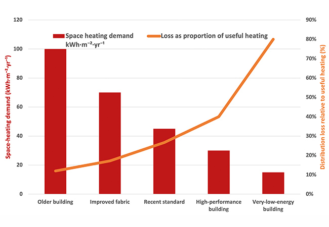
Figure 1: Conceptual illustration showing how constant annual distribution heat losses (assumed here to be 12kWh·m-²) become an increasing proportion of operational energy use as useful space-heating demand falls. The values are illustrative and are intended solely to demonstrate the underlying principle
Distribution losses and unwanted heat gains
The growth of communal heating systems has fundamentally changed the way heat is distributed within residential buildings.
Primary distribution pipework frequently operates continuously to maintain DHW availability. Every metre of heated pipe therefore becomes a permanent source of background heat. Guidance for communal heat networks, including the London Heat Network Manual2, specifically identifies corridor overheating as an important design consideration, recommending insulation not only to reduce energy losses, but also to minimise unwanted heat gains.
Several design features can contribute:
- Long horizontal distribution runs
- Permanently circulating primary circuits
- DHW return loops
- Poorly insulated valves, strainers and flanges
- Bypass arrangements
- Continuously heated service risers.
Communal corridors often have no opening windows, limited ventilation and no cooling provision. Heat released into service cupboards and ceiling voids gradually migrates into circulation spaces, lift lobbies and neighbouring apartments.
Pipework heat loss is rarely the sole cause of overheating. Solar gains, occupancy and ventilation usually dominate peak summer temperatures. Nevertheless, distribution pipework provides a continuous heat source throughout the year and should therefore be considered alongside other overheating mitigation measures. During winter, some of this heat may provide incidental space heating. During warmer months, however, it becomes an unwanted internal heat gain that can contribute to overheating or increase cooling demand.
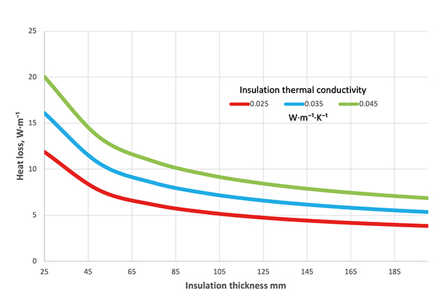
Figure 2: Indicative heat loss, W·m-¹, for horizontal 63mm outside diameter steel pipe at 70°C surrounded by an environment at 20°C with insulation of thermal conductivities 0.025, 0.035 and 0.045W·m-¹·K-¹, calculated with an assumed combined external heat transfer coefficient of 8W·m-²·K-¹
Pipe insulation: only part of the solution
Thicker insulation is often the first response to overheating concerns. While improving insulation almost always reduces distribution losses, it should not be viewed as the only solution.
Heat emissions depend upon insulation thickness, water temperature, pipe length, operating hours and installation quality. Effective design therefore considers the complete system.
Potential measures include:
- Reducing operating temperatures
- Demand-controlled DHW recirculation
- Shortening distribution routes
- Improving pipe routing
- Reducing unnecessary bypasses
- Lowering return temperatures
- Decentralising plant where appropriate.
The objective is not simply to specify thicker insulation, but also to minimise unnecessary heat transfer throughout the distribution network. The greatest reductions in heat loss may be achieved by reducing the amount of hot pipework in the building, rather than simply insulating it more heavily.
Figure 2: Indicative heat loss, W·m-¹, for horizontal 63mm outside diameter steel pipe at 70°C surrounded by an environment at 20°C with insulation of thermal conductivities 0.025, 0.035 and 0.045W·m-¹·K-¹, calculated with an assumed combined external heat transfer coefficient of 8W·m-²·K-¹
Low-temperature heating transformation
Lower-temperature heating systems offer benefits extending well beyond improved heat pump efficiency. Because pipework heat loss depends largely upon temperature difference, reducing flow temperatures reduces heat loss from every metre of pipework. Less heat is lost from the distribution system and less unwanted heat enters occupied spaces.
Lower temperatures also improve heat pump coefficient of performance (COP) and reduce distribution losses within communal heating systems and district heat networks.
Achieving these benefits depends upon maintaining a healthy system temperature difference. Good hydraulic design, commissioning and balancing enable lower return temperatures and improved system efficiency.
These principles are increasingly reflected in emerging heat network performance frameworks. In the UK, for example, the Heat Network Technical Assurance Scheme (HNTAS)3 introduces an important performance indicator, the volume weighted average return temperature (VWART), which measures average return temperature across the network. Lower VWART values generally indicate more efficient heat transfer and reduced distribution losses.
Pipe insulation, hydraulic design, commissioning and operating temperature should therefore be viewed as complementary elements of the same strategy, rather than separate design decisions. The most effective pipework is not simply the best insulated, it is the pipework that carries the minimum amount of heat, at the lowest practical temperature, for the shortest practical distance.
Installation quality
Even the best specification delivers little benefit if insulation is poorly installed. Exposed valves, strainers, flanges, unions and compression fittings are common sources of heat loss, as illustrated in Figure 3. Likewise, insulation compressed beneath support brackets, damaged during maintenance or cut short around hangers creates thermal bridges that increase heat transfer. Although fittings typically represent only a small proportion of the total pipe length, their larger surface area and frequent lack of insulation mean they can contribute a disproportionately large share of the overall heat loss.
Designers should therefore consider insulation continuity at supports, the use of removable insulation jackets for valves and strainers, and robust site inspection. They should also recognise that insulation is routinely removed during maintenance, so specifying durable, reusable jackets helps ensure that insulation is reinstated after servicing.
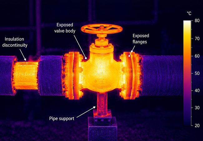
Figure 3: Illustrative infrared image showing the disproportionate heat losses that occur at exposed valves, flanges and insulation discontinuities. Such thermal bridges can contribute significantly to distribution losses, despite the surrounding pipework being well insulated
Looking beyond compliance
Pipework insulation is becoming an operational performance issue rather than simply a specification exercise. Post-occupancy evaluation, Soft Landings4 and digital building analytics increasingly allow engineers to verify system performance after handover, identifying excessive return temperatures, continuously operating circulation pumps and abnormal distribution losses.
Across many countries, guidance on overheating, operational performance and heat network efficiency increasingly encourages designers to consider how buildings perform in use, rather than simply at the design stage. In the UK, examples include Approved Document O5, CIBSE TM596 and HNTAS. Future climate projections further strengthen the case for reducing unwanted internal heat gains wherever practicable.
Good insulation remains essential, but the highest-performing buildings will not necessarily be those with the thickest insulation. They will be the buildings that minimise unnecessary heat transfer through good system architecture, low operating temperatures, intelligent controls, high-quality installation and effective commissioning. The most efficient distribution system is the one that transports only the heat that is required, only where it is needed and only for as long as necessary.
Pipework insulation is no longer simply a necessary compliance exercise. It is an integral part of delivering buildings that are energy efficient, resilient and comfortable to occupy throughout their entire operational life.
© Tim Dwyer 2026.
References:
1 BSI. BS 5422:2023. Method for specifying thermal insulating materials for pipes, tanks, vessels, ductwork and equipment operating within the temperature range –40°C to +700°C. London: BSI; 2023.
2 Greater London Authority. London Heat Network Manual II. 2nd ed. London: Greater London Authority; 2021.
3 Department for Energy Security and Net Zero. Heat Network Technical Assurance Scheme (HNTAS). London: Department for Energy Security and Net Zero; 2026.
4 BSRIA. Soft Landings Framework 2023. BG 54/2023. Bracknell: BSRIA; 2023.
5 HM Government. Approved Document O: Overheating. The Building Regulations 2010. London: HMSO; 2021.
6 CIBSE. TM59: Design methodology for the assessment of overheating risk in homes. London: CIBSE; 2017.