For an alternative way to access this module, CIBSE member, Jos Brownlie provides a video reading the module: Module 262 recording

CPD sponsor
Doorways represent one of the most complex and least predictable elements of the building thermal envelope. While walls, roofs and glazing are designed as static thermal boundaries with defined U-values and airtightness targets, an open doorway behaves very differently. When a door is open, the separation between indoor and outdoor environments is no longer defined by insulation or airtightness but by fluid flow driven by pressure differences and buoyancy forces.
In this sense, a doorway should be understood as a dynamic thermal boundary. Airflow through the opening is governed by the interaction of temperature differences, wind pressure, and building ventilation systems. In buildings with frequent door use – including retail units, restaurants, logistics facilities and transport hubs – these flows can dominate heat loss and significantly influence local thermal comfort.
Air curtains attempt to control this boundary condition by generating a high-velocity air jet across the doorway. This jet forms an aerodynamic barrier, reducing the exchange of air between two environments while maintaining visibility and unobstructed access.
However, their performance is fundamentally governed by building physics: the behaviour of turbulent jets, pressure-driven infiltration and the interaction between airflow and thermal gradients.
This CPD explores the physics underlying air curtain operation, the forces driving airflow through doorways, the conditions under which air curtains succeed or fail, and the challenges associated with modelling their performance in building energy simulations.
Jet behaviour and aerodynamic sealing
The performance of an air curtain depends primarily on the behaviour of the air jet it generates. The jet is typically discharged from a narrow slot along the head of the doorway at relatively high velocity.
From a fluid mechanics perspective, this flow behaves as a turbulent plane jet. Its velocity is highest at the discharge grille and gradually decreases as the jet travels downward toward the floor.
The jet typically passes through three distinct regions as follows:
Discharge region: immediately after the nozzle, the airflow is influenced by the internal geometry of the unit. Turbulence generated by the fan and grille affects the structure of the emerging jet.
Established jet region: further downstream, the jet becomes a coherent downward airflow. As it travels, the jet entrains surrounding air from both sides of the doorway. This entrainment process increases the jet thickness and reduces its centreline velocity.
Floor interaction region: when the jet reaches the floor, the airflow decelerates and splits horizontally. The air then returns to each side of the opening, completing the circulation pattern that maintains separation between the two environments.
For an air curtain to operate effectively, the jet must reach the floor while retaining sufficient momentum to resist external forces acting across the doorway.
Jet force and momentum
The ability of an air curtain to resist infiltration depends on the momentum of the air jet, rather than simply the volume of air delivered. Resistance depends on the momentum flux of the jet rather than simply volumetric airflow rate. For a plane jet issuing from a slot, the approximate momentum flux per unit width can be expressed as:
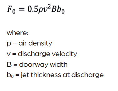
This relationship highlights an important design principle: jet force increases with the square of velocity. Consequently, small increases in discharge velocity can significantly increase the resistance of the air curtain to external pressure differences. Conversely, systems designed purely around volumetric airflow (m³·h-1) may deliver insufficient jet momentum if discharge velocities are too low.
This distinction explains why two air curtains with similar airflow rates can exhibit very different sealing performance.
As the jet travels downward, entraining surrounding air from both sides of the doorway, turbulent jet theory shows that this entrainment rapidly increases the total airflow within the jet. Therefore, much of the air in the curtain originates from the surrounding environment rather than the supply air from the unit.
Importance of velocity optimisation
Air curtain performance depends strongly on the discharge velocity.
If the velocity is too low, the jet loses momentum before reaching the floor. The airflow then becomes unstable and may be deflected either inward or outward. Under these conditions, the unit behaves more like an over-door heater than an aerodynamic barrier.
If the velocity is too high, the jet strikes the floor with excessive force, generating strong turbulence and mixing between the indoor and outdoor air masses. This turbulence disrupts the separation effect and can actually increase air exchange.
Effective design therefore requires optimisation of jet velocity, balancing sufficient momentum against excessive turbulence. Correct commissioning is essential to achieve this operating condition. Energy codes, such as ASHRAE 90.1, mandate that the air curtain must be commissioned to maintain a jet velocity of not less than 2m.s-1 150mm above the floor.
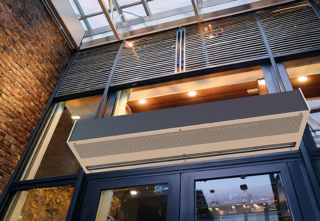
Figure 1: air curtains can be used as a solution to control the dynamic thermal boundary presented by doorways (Source: JS Air Curtains)
Infiltration through open doorways
When a doorway is open, airflow across the opening is primarily driven by two physical mechanisms: buoyancy (stack effect) and wind pressure. These forces generate pressure differences that cause air exchange between the two environments.
Buoyancy-driven airflow
Warmer air is less dense than cooler air so buoyancy forces cause it to rise and escape through the upper portion of the doorway, while denser cooler air enters at low level. This creates a bi-directional flow pattern. At some point within the doorway height, a neutral pressure plane exists where the airflow velocity is zero. Above this plane, air flows outward from the warmer space; below it, cooler air flows inward. This can be represented in the equation:
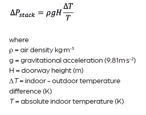
Although the net volumetric airflow across the opening may be close to zero, the thermal energy exchange can be significant because conditioned air is continuously replaced by unconditioned air. The magnitude of this exchange increases with:
- Temperature difference between indoor and outdoor environments
- Doorway height and width
- Frequency of door opening
Wind-driven infiltration
Wind introduces additional pressure differences across the building envelope. The resulting airflow through an open doorway depends on:
- Local wind speed
- Building exposure
- Façade pressure coefficients
- Building airtightness
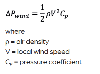
As a result, even modest increases in wind velocity can produce significant pressure differences across an opening. In practice, the air curtain must overcome the combined pressure effects of wind and stack to maintain its separation function.
Performance limits and failure modes
There is some evidence to show that air curtains can provide significant energy savings when correctly applied. For example, field studies in retail buildings have reported HVAC energy reductions exceeding 30% in high-traffic entrances.2 Several common failure modes exist:
- Incorrect discharge velocity: if the jet velocity is not correctly set, the curtain may collapse before reaching the floor or generate excessive turbulence at
floor level. - Incorrect discharge angle: most air curtains are installed to discharge air at an angle of between 10° and 20° outward from the vertical, directed slightly toward the exterior side of the doorway.
- Building pressure imbalance: if the mechanical ventilation system produces excessive negative pressure, outdoor air will be drawn into the building, potentially overwhelming the air curtain jet. Similarly, strong positive pressure may push indoor air outward through the doorway.
- Poor building airtightness: large openings elsewhere in the building envelope can create internal cross-draughts. These flows can deflect the air curtain jet and significantly reduce its effectiveness. Examples include open doors on opposite façades or open roof vents.
Environmental limits
Even under ideal conditions, air curtains operate within defined environmental limits. Typical commercial air curtains are designed to resist modest façade pressure differences, often corresponding to wind speeds of around 3m·s-1 to 5m·s-1 at the doorway. At these velocities, the dynamic pressure is typically in the range 5Pa to 15Pa, depending on local pressure coefficients and
building exposure.
Air curtains are also subject to practical size limits. Standard products typically cover openings up to around 8m in width or height, with larger installations requiring custom systems.
Thermal comfort considerations
At pedestrian entrances, air curtains must also satisfy comfort requirements. People passing through the doorway briefly experience the high-velocity airflow generated by the curtain. Exposure velocities typically range from 3m·s-1 to 10m·s-1, usually lasting less than one second.
To maintain acceptable comfort, discharge air temperatures are typically limited to around 40°C, while air velocities and turbulence within the occupied zone must remain low enough to avoid draught discomfort, consistent with the comfort criteria described in CIBSE Guide A and ASHRAE Standard 55.
Noise must also be considered, particularly where air curtains are installed above frequently used pedestrian entrances. These units typically contain high-speed fans and discharge air at relatively high velocity, so sound levels close to the doorway can be noticeable if the unit is poorly selected or operated at excessive speed.
CIBSE Guide B provides recommended background noise criteria for different building types. For retail areas, restaurants and circulation spaces these typically fall in the range NR 50-60. In practice, air curtains should be selected and controlled so that their contribution does not significantly exceed these background levels within the occupied space.
Energy modelling considerations
From a building physics perspective, modelling air curtains presents a significant challenge.
In the UK, Building Regulation compliance calculations are usually performed using the Simplified Building Energy Model (SBEM) within the National Calculation Methodology.
SBEM does not explicitly model airflow through open doors or the aerodynamic separation created by air curtains. As a result, the reduction in infiltration provided by an air curtain cannot usually be represented directly in standard SBEM calculations.
Instead, designers typically represent the air curtain as a heating or cooling device and ensure that its mechanical performance is accurately defined. Key parameters include: seasonal efficiency (seasonal coefficient of performance (SCOP) or seasonal energy efficiency ratio (SEER)); specific fan power (SFP); and system control strategy.
Where air curtains incorporate heat pumps, the system should be modelled accordingly to avoid default assumptions that may underestimate efficiency.
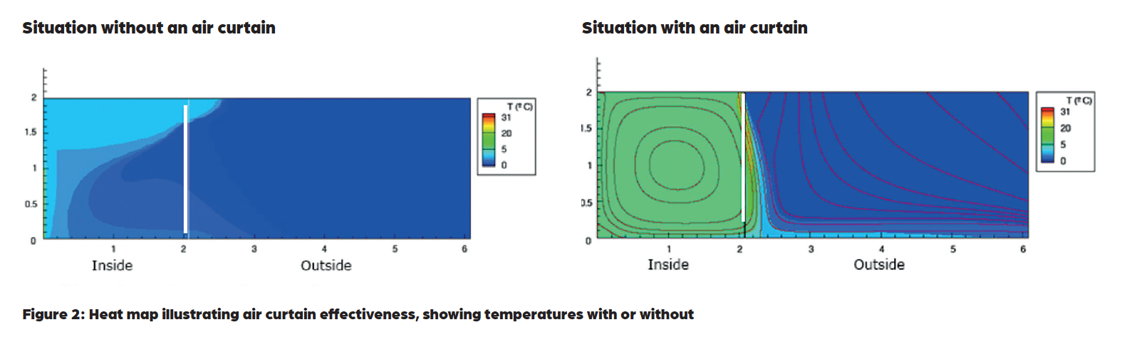
Figure 2: Heat map illustrating air curtain effectiveness, showing temperatures with or without
Dynamic simulation and airflow modelling
Where more detailed analysis is required, designers may use dynamic simulation models (DSMs). These tools can incorporate airflow network modelling, which allows pressure-driven air movement between zones to be simulated. Doorways can be represented as large openings with defined flow coefficients, while wind pressure and stack effects can be included explicitly.
More advanced studies may use computational fluid dynamics (CFD) to analyse the behaviour of the air curtain jet, including entrainment, turbulence and interaction with wind. Although these methods require more detailed modelling effort, they can provide valuable insight into: local comfort conditions near entrances; infiltration heat losses; and optimisation of air curtain velocity and placement.
Integration with low carbon heating systems
Air curtains can operate with several heat sources, including electric heaters, hot-water coils and heat pumps. Increasingly, air curtains are being integrated with low-temperature heat pump systems. This can be achieved using either direct expansion (DX) coils connected to variable refrigerant flow (VRF) or split heat pump systems; or low-temperature hot-water (LTHW) coils supplied by air source or ground source heat pumps.
Air curtains supplied by heat pumps can operate more efficiently than units using electric resistance heating, because the heat pump provides heat at a higher coefficient of performance (COP). Hybrid designs are also available, combining a heat pump coil with a small electric heater that provides supplementary heat during defrost cycles or peak loads.
Control strategies
Control systems play a critical role in achieving efficient operation. Older air curtain installations often relied on manual switches with fixed fan speeds and heating outputs. This approach can lead to unnecessary energy consumption and inconsistent performance.
Modern systems use automated control strategies. Door sensors activate the air curtain when the entrance is open, while temperature sensors monitor indoor and outdoor conditions. Advanced control algorithms can then adjust airflow velocity and heating output independently to maintain optimal jet stability and thermal performance.
Integration with building management systems enables coordination with the wider HVAC system. Communication protocols such as Modbus and BACnet can allow monitoring, diagnostics and remote optimisation.
Meeting the challenge of open doorways
Open doorways represent a highly dynamic component of the building envelope.
Air curtains attempt to manage this interface by generating a turbulent jet that acts as a dynamic aerodynamic boundary.
Understanding the underlying building physics – jet behaviour, pressure differentials and airflow interaction – is essential for effective design.
When properly selected, commissioned and integrated with ventilation systems, low carbon heating technologies and intelligent controls, air curtains can significantly improve environmental control at building entrances and reduce energy losses at one of the most challenging points in the thermal envelope.
© Andy Pearson, 2026.
References:
1 ASHRAE Handbook chapter 16. Ventilation and Infiltration
2 Gil-López, T et al (2013). Experimental analysis of energy savings and hygrothermal conditions improvement by means of air curtains in stores with intensive pedestrian traffic. Energy and Buildings.