
The Green Smart Community Integrated Energy System (GreenSCIES) in the London Borough of Islington is intended to use waste heat and integrate grid power to help reduce carbon emissions by up to 80% compared with current, conventional systems. The energy network should help reduce the cost of low carbon heat to residents and tackle fuel poverty in the borough. The vision is that GreenSCIES will be rolled out over a significant area of Islington, so it can supply low carbon heat to more than 10,000 residents in 3,500 homes, along with up to 70 businesses.
Following a feasibility study led by London South Bank University, the focus now is on developing the design and commercial delivery packages for the New River area part of Islington to test the concept. Silver EMS, a heat network specialist and MEP consultancy, is delivering a RIBA stage 2+ design for the New River scheme. It is working with Cullinan Studio, which is developing the architectural design of the scheme, and other partners that are providing specialist support services.
This is potentially a major solution for reaching net zero SLES in cities by integrating infrastructure
‘Ultra-low temperature 5th generation heat networks present a major opportunity to decarbonise whole areas where there are large heating and cooling demands that can be shared across an ambient loop,’ says Phil Jones, of Building Low Carbon Solutions, who led on the development of the GreenSCIES concept design.
‘This is potentially a major solution for reaching net-zero smart local energy systems (SLES) in cities by integrating infrastructure like heat networks, heat pumps, thermal storage electric vehicles (EVs) and PVs.’
Bi-directional flow
The New River scheme will include three council-owned residential blocks, two university campuses, a theatre, primary school, library and, crucially, a data centre. When complete, this section of the scheme alone is expected to save more than 5,000 tonnes of CO2e annually. The layout options for the network under consideration, including the pipework route, connected buildings and energy centres, are shown in Figure 1.
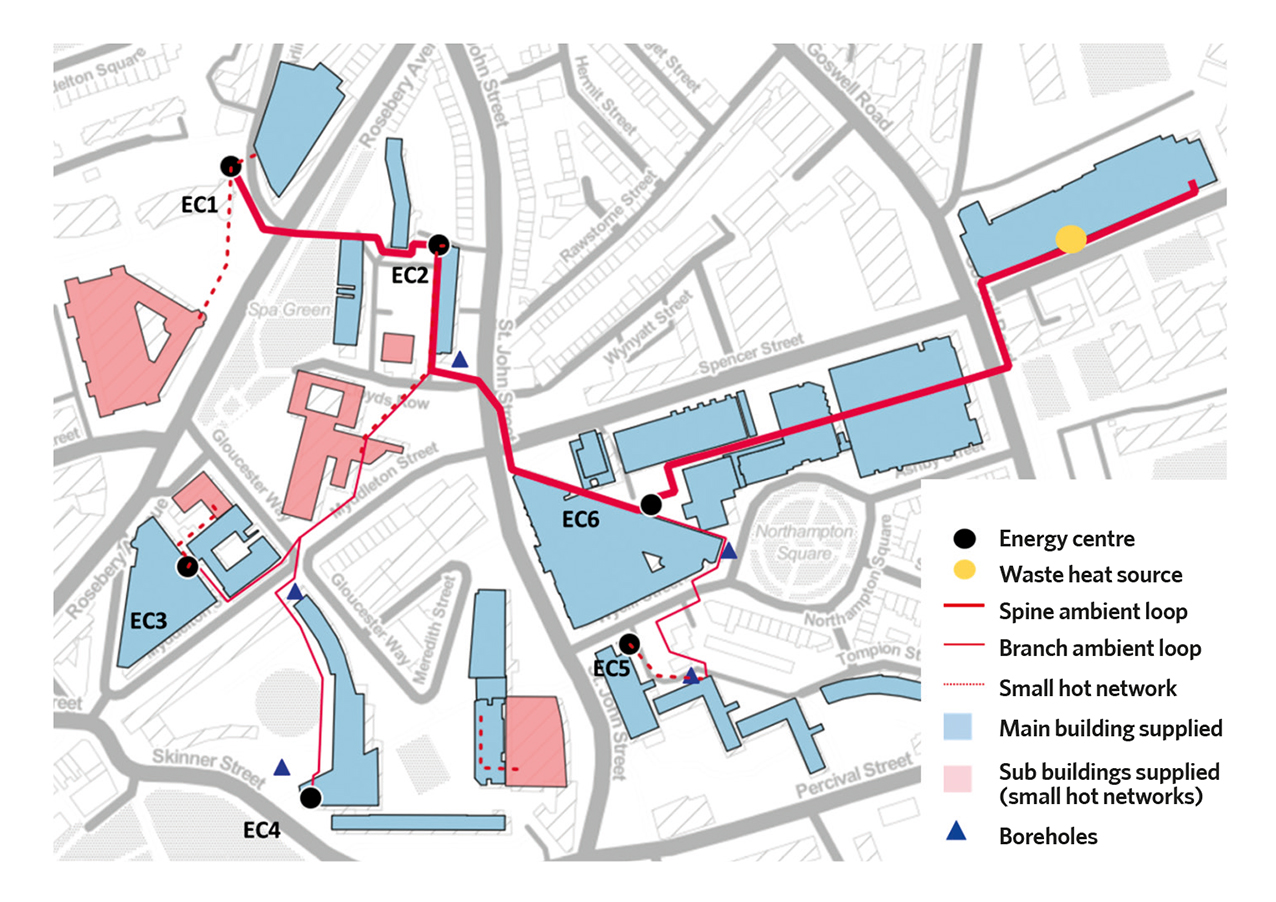
Figure 1: Provisional New River scheme layout
Fundamental to the scheme is a two-pipe ambient loop district energy network. This will allow low-grade thermal energy to be exchanged between buildings requiring heating and cooling. The loop is formed from two pipes: one warm, one cold (Figure 3).
‘The design will permit bi-directional flow within the pipes, to allow energy exchange to take place between heating and cooling customers at different times and in different locations, depending on where demand is at any given time,’ says Dr Anthony Riddle, technical director of Silver EMS. ‘Circulating pumps will be located across the network at individual customers’ energy centres, facilitating the bi-directional flow concept and enabling the network to be readily expanded as customers are connected in the future.’
An existing data centre will provide the primary source of waste heat for the New River scheme. It will be connected to the ambient loop through a heat exchanger substation. ‘This will recover heat from the return of the chilled water primary circuit, before returning it to the data centre chillers,’ says Riddle.
Heat recovered from the data centre will be distributed by the warmer of the two pipes. Initially, this will be at about 15oC but the network and heat exchanger substation will be designed to accommodate increases in heat recovery temperature in line with anticipated enhancements to efficiency of customer cooling systems.
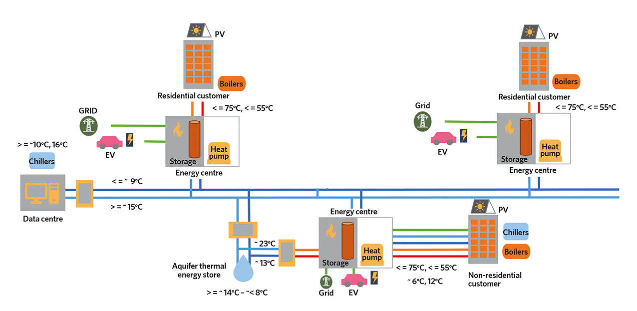
Figure 3: Schematic of ambient loop network
A series of dedicated decentralised energy centres will connect each heating customer to the ambient loop through packaged heat pump systems coupled to large-capacity thermal stores. Cooling customers, including the data centre, will connect to the loop through dedicated decentralised energy centres containing heat exchanger substations.
Cooled water leaving heating customers’ heat pump evaporator circuit heat exchangers will be returned to the data centre and other cooling customers through the cooler of the two ambient loop pipes. It will provide cooling at a temperature just sufficient to meet customer requirements.
At first, this will be around 10oC but the heat pumps, the ambient loop network and cooling customer heat exchanger substations will be designed to accommodate increases in heat recovery temperature in line with anticipated enhancements to efficiency of customer cooling systems.
Balancing loads
To maximise both the economic and carbon benefits of using an ambient loop, it will be important to balance the heating demand with the cooling load across the network. It is also key to maintain the temperature of the cold loop at a low enough value to meet the cooling requirements of the data centre and other customers.
‘This presents an interesting control challenge for the network, a critical objective being to prevent uncontrolled mixing of the warm and cold pipes so as to avoid diluting the quality of cooling delivered to the cooling customers,’ Riddle says. Optimisation of the hydraulic and control concepts are ongoing and will be carried out by the end of this year, once the preferred network route has been established. Hysopt software will be used to assist in this process.
When it is not possible to balance short-term heating and cooling loads across the network, the plan is to use an aquifer thermal energy storage (ATES) system to supplement the shortfall. This will also provide a means to store surplus energy inter-seasonally.
Three bi-directional borehole pairs will transfer energy between the ambient loop and the warm and cold sides of the ATES system. Heat transfer will take place across a heat exchanger substation. The hydro geology of the aquifer is being modelled by Agua Enodo. Preliminary results show the ATES is viable with varying degrees of efficiency. As yet, no trial boreholes have been drilled.
‘Through a combination of inter-seasonal storage and operational setpoint control of various distributed assets within the network, the intention is to allow the future scheme operator to vary the temperature difference between the warm and cold pipes, particularly when demand is high. This will reduce pumping energy requirements during these periods, cutting the carbon penalty of delivering heat and coolth,’ says Riddle.
To ensure an uninterrupted supply of coolth, the scheme will be configured so that one of the heat pumps is able to operate as a water-cooled chiller at times when demand for heat is low and the ATES has been depleted or it is more cost-effective to generate coolth using the chiller as opposed to discharging the ATES (shown as A-loop chiller in Figure 2).
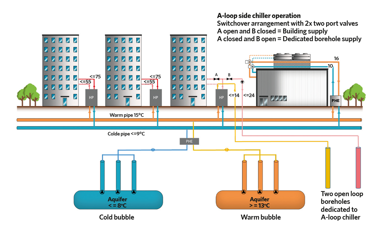
Figure 2: The ATES concept with an A-loop chiller (Revesz et al 2021)
In this mode, the heat pump will condition the cold side of the loop through its evaporator circuit, but heat rejected from the condenser circuit will be discharged to the aquifer. ‘This will reduce reliance on customer heat pumps and improve financial returns,’ says Riddle. ‘A number of techniques and options for doing this are under consideration in the ongoing concept development.’
‘The aim is for the network to be capable of operating seamlessly and automatically in a number of operating modes to cater for varying load conditions and for future expansion of the network and data centre, which could significantly increase the amount of heat available,’ says Riddle. Islington Council will be the biggest user of waste heat. As the ambient loop becomes established, other customers with heating loads will be able to use waste heat from the data centre and those with cooling systems will be able to reject waste heat into the network.
Pipe routes are still being established through site surveying and utility mapping. A big advantage of the loop being at ambient temperature is that the pipework will be at a similar temperature to that of the ground and outside air. This helps limit external pipe diameter requirements and minimises heat losses. Architect Cullinan Studio has investigated running pipes above ground in key locations to avoid the complications of having to bury it at complex crossings within Islington’s utility-congested streets.
Branch connections will link smaller customers to the main decentralised energy centres connected to the loop. The heat pumps will typically be specified to generate at up to 75oC to meet the needs of the existing heating and hot-water systems of connected buildings.
‘The heat pumps will be specified to have the ability to operate at lower temperatures so that, over time, generation temperatures can be relaxed on a building-by-building basis as owners invest in improvements to the fabric and/or to space heating and domestic hot water distribution systems,’ says Riddle.
The scheme is being designed to fully displace fossil fuel requirements for space heating and domestic hot water. ‘However, the intention is that buildings with existing heat-generation assets will retain these for back-up purposes in the early years,’ explains Riddle.
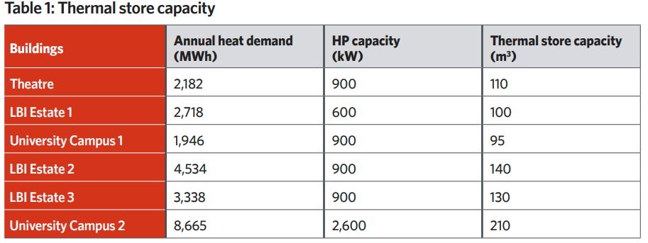
The thermal stores have been based on techno-economic optimsation carried out by Carbon Decent (see Table 1: ‘Thermal store capacity’). The heat pumps will charge the thermal storages when grid electricity prices are at their lowest, either overnight or during the day when there is surplus electricity production on the system.
When the price is lowest should also coincide with low carbon content in the grid. Thermal stores will allow heat pumps to operate continuously for a longer period of time, rather than cycle on and off, which will help maximise operational life. Although heat pumps will be specified with variable speed compressors and drives, they will typically be set to run at constant load, charging the thermal stores as they do so. This simplifies hydraulic control of the ambient loop.
The techno-economic proposition of flexible operation of the assets has been investigated through techno-economic modelling led by Chris Dunham (Carbon Descent). It has shown that, as well as making significant carbon savings, the concept can deliver affordable heating to residents and competitively priced cooling and EV charging.
A number of heat pump models and refrigerant types are being considered based on coefficient of performance (COP) and capital cost. LSBU’s Heating and Cooling Team, led by Graeme Maidment and Akos Revesz, carried out a detailed investigation comparing the life-cycle performance of a number of different heat pump units.
‘The intention is to retain flexibility in the design and keep the accompanying technical specifications relatively loose to ensure that, when the scheme goes to market, supply of the heat pumps will not be confined to particular technologies, manufacturers or refrigerant types. It will also be important to future-proof the designs to allow a range of latest generation refrigerant technologies to be implemented safely and cost-effectively over the life of the network,’ says Riddle.
Various configurations in the energy centres are being assessed, including using multiple heat pumps operating with condensers in series to reduce the temperature increase required by each individual heat pump to improve operating efficiency. LSBU found that by arranging multiple heat pumps with condensers and evaporators in series COP could be increased by up to 30%.
This arrangement has the benefit of being able to take a heat pump out of operation and still run the remaining units. The performance benefits of connecting the heat pumps in series needs to be offset against the additional capital cost and the increased requirement for plant space.
Plant space is a major challenge when retrofitting the energy network to existing buildings. In general, there is insufficient space in the plantrooms of most buildings to accommodate the additional requirements, which is why the scheme has gone down the route of constructing the new energy centres. To minimise the space required by the thermal stores, the use of phase change material (PCM) thermal storage is also being considered.
The distributed energy centres allow the installation of local hot networks to give heat to smaller customers without the need to connect to the loop. This has benefits where there are space limitations or where the connected loads are too small to warrant additional investment.
It is in the energy centres where the heat network is integrated with building-mounted PV systems and EV charging points. The decentralised energy centres effectively become the hub of a ‘micro-grid’. These could also incorporate grid electricity storage provided by the batteries from connected EVs. This will enable the system to respond to electricity grid demand and tariffs. AI will be used to help flex electricity demands from heat pumps and electric vehicle charging in response to price signals from the grid and the intermittent output of solar power.
Implementing schemes like this, with its economic, community, and environmental benefits will be critical if we are to reach the target of net-zero carbon for existing buildings.
‘GreenSCIES will contribute to London’s zero-carbon ambition by decarbonising the local energy system in Islington as part of its Net Zero Carbon Vision 2030,’ says Revesz, technical lead at GreenSCIES, who says the project is looking at scaling up the concept. ‘We strongly believe that the implementation of schemes like this could provide a roadmap to help towns and cities across the UK and elsewhere achieve net-zero targets on time.’
GreenSCIES project team
The consortium includes the following partners:
- Building Low Carbon Solutions
- Carbon Data Resources
- Carbon Descent Projects
- Cenex
- Consortio
- Cullinan Studio
- E.ON
- Grid Edge
- Hanger 19
- London Borough of Islington
- London South Bank University
- Operational Intelligence
- Repowering London
- Silver Energy Management Solutions
- Transport for London
- West Midlands Combined Authority