
The term ‘safety valve’ would typically encompass relief valves, pressure-relief valves and safety relief valves, and this ‘pressure equipment’ – as it is referred to in EU directives – is classified by group according to the level of hazard. Fluids used in building services engineering would most likely be those referred to in the standards as being in group 2 (whereas group 1 is for those classified as ‘hazardous’). The fluid group would normally be used as part of the assessment of risk ‘category’; however, general purpose safety valves will, in any case, fall under the most stringent category 4, which defines the level of design and production quality control to ensure conformity that allows a safety device to bear the legally required CE mark.
In the UK, specific requirements for system safety are principally encompassed by the Pressure Equipment (Safety) Regulations 20161 and the Simple Pressure Vessels (Safety) Regulations 20162 that implement Directives 2014/68/EU, the Pressure Equipment Directive (PED), and 2014/29/EU, the Simple Pressure Vessels Directive (SPVD). The regulations specifically come into play when the systems are operating at pressures greater that 50kPa (0.5bar, 5.1m water head).
The recently revised part 1 of Safety devices for protection against excessive pressure, BS EN ISO 4126:2019, specifies the general requirements for safety valves and the testing techniques for valves set at pressures of 0.1bar gauge and above. (This standard supersedes the withdrawn, but oft quoted, UK standard BS 6759.3) ISO 4126 has 11 parts that consider the different requirements to provide against excessive pressure. It describes a safety valve as ‘a valve which automatically, without the assistance of any energy other than that of the fluid concerned, discharges a quantity of the fluid so as to prevent a predetermined safe pressure being exceeded, and which is designed to re-close and prevent further flow of fluid after normal pressure conditions of service have been restored’.
A safety valve may provide protection against hazards arising from a number of scenarios. This could, for example, be a blocked vessel or pipework discharge; excessive heat from external sources, such as the sun, or other equipment that can cause the fluid within the pipework to expand; system thermal expansion from heat fluctuations beyond the expected design conditions; and failure of a pipeline component, such as an ineffective, failed or tampered control valve or other component that may prevent adequate, or any, discharge.
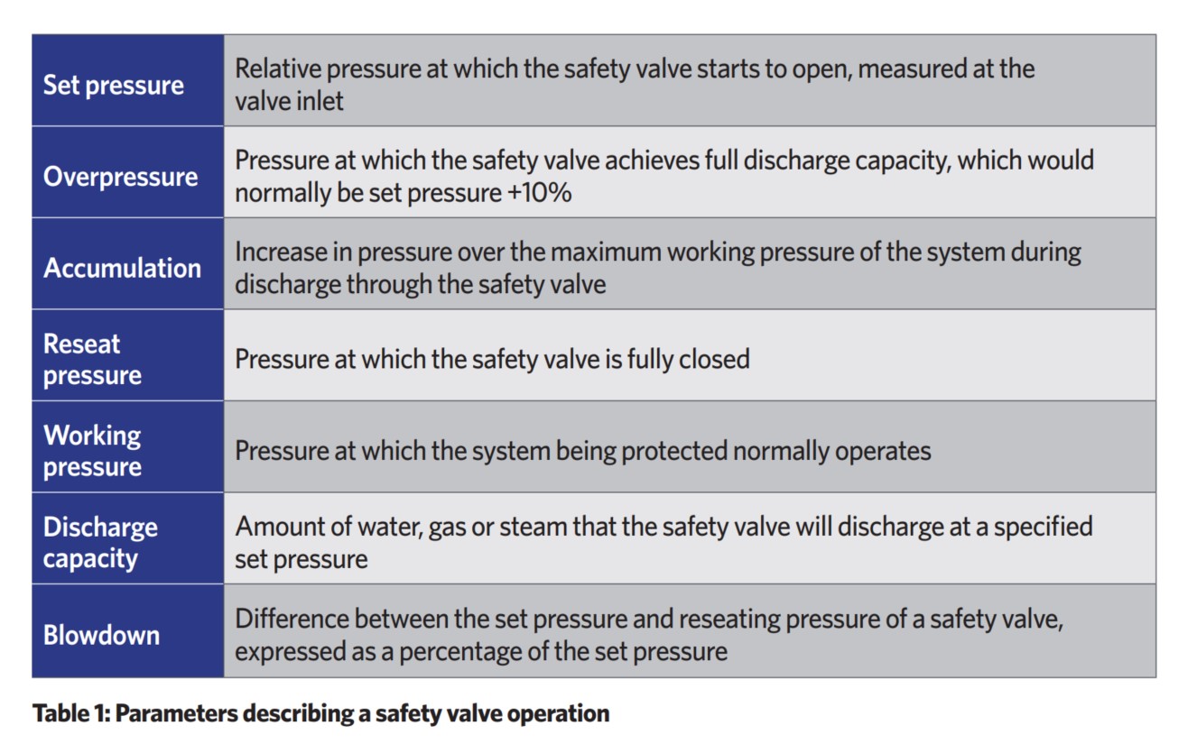
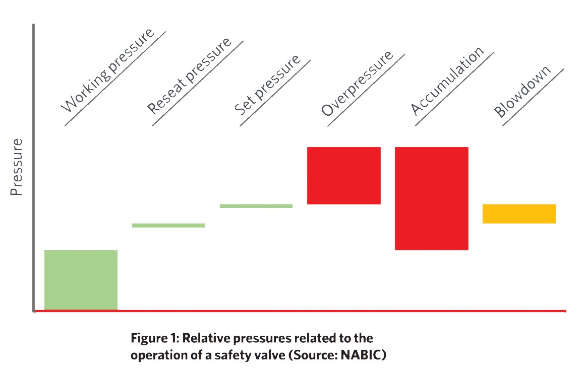
When evaluating the expected performance of a valve, some terms are commonly used to describe valve operation, as shown in Table 1 and illustrated in Figure 1.
Direct spring safety valves, as illustrated in Figure 2 and Figure 3A, are commonly used within building services systems. The spring is precompressed to apply force downwards on the disc, holding it onto the seat to maintain a pressure-tight seal. If the system pressure increases beyond a predetermined value, it overcomes the spring force and flow commences.
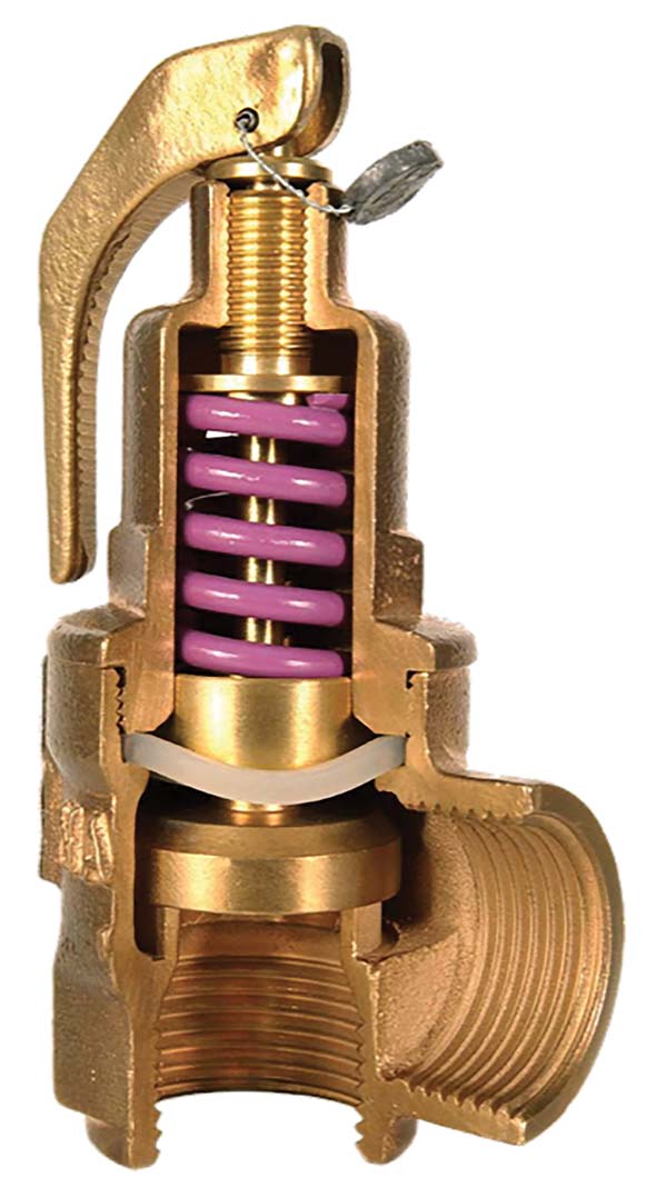
Figure 2: Example of a direct spring safety valve
Figure 3b shows a combined temperature- and pressure-relief valve. In addition to providing pressure protection, this valve also features a thermostatic probe, which gives protection against excessive temperature. If the system pressure or temperature increases beyond the set point, the spring force is overcome and flow commences. Each of these lift mechanisms works independently of each other, but are managed through a common seat and disc arrangement. Typically, the valve can be temperature set to between -20°C to 95°C.
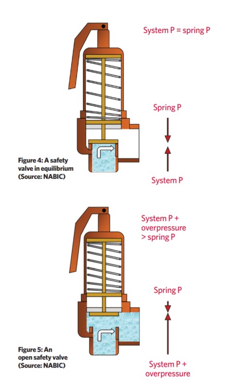
The operation of a safety valve can be considered in three states: in equilibrium, open, and closed. When the closing forces acting to close the safety valve are in balance with the opening forces acting to open it, it is in a state of equilibrium (defined in ISO 4126 as the ‘set pressure’). This is illustrated in Figure 4 for a safety valve where the valve seat and disc are just in contact. In this position, there is no flow, but flow will commence if the system pressure rises.
When fully open, as shown in Figure 5, the safety valve can pass the maximum/rated capacity at the specified overpressure (not the set pressure). For the safety valve to remain open, the force from the fluid on the underside of the disc must exceed the equilibrium force (the applied spring and backpressure force).
A valve will be fully closed when the closing force (spring + backpressure) exceeds the opening force. The term blowdown is used to represent the difference between the set pressure and reseating pressure of a safety valve, expressed as a percentage of the set pressure, so…
System pressure – blowdown pressure = reseat pressure
Safety valves should be carefully selected and sized for the specific application to ensure that they have sufficient discharge capability. Sizing will directly influence valve performance. For example, oversized valves will partially lift at set pressure and then reseat. This can potentially cause ‘chattering’ of the disc and damage to the seat and disc surfaces. Oversized valves may also lead to the release of excessive amounts of fluid.
There are three main considerations when sizing and selecting an appropriate, and correctly sized, safety valve – application, set pressure and discharge capacity.

Consideration of the application includes the location of the safety valve. For example, it may be employed to protect a boiler, to relieve a pump overpressure, or to ensure the integrity of a vessel (tank). The fluid that is in the system – in building services it is likely to be water, air or steam – will influence the choice of valve material and design.
The set pressure of the safety valve will need to be established. If the required set pressure has not been specified at the time of sizing, this can be calculated from the working pressure of the system (at the point in the system where the valve is to be installed). If the working pressure is known, the set pressure may be established using empirical data established by manufacturers and building operators. So, for example, a manufacturer4 recommends that, for a liquid/water system, set pressure would be the working pressure +0.7bar, or the working pressure x 1.1 (whichever is the greater).
Careful consideration of the requirements is needed where the only available information is the maximum pressure rating/output of a heat source, such as when protecting a system with a boiler or plate heat exchanger. This value is simply a statement of the maximum capability of the appliance and it is very unlikely to represent the actual working pressure. The UK’s Health and Safety Executive (HSE) publishes a useful approved code of practice and guidance document – L122 Safety of pressure systems5 – which cautions that the terminology used for different types of systems will vary. For example, the safe operating limit for a boiler may be known as the ‘maximum permissible working pressure’, whereas the safe operating limits for refrigeration plant will be expressed in terms of minimum and maximum temperatures. In cases of doubt, or where information is not clear, it is recommended that further detailed information should be sought from the manufacturer or other competent organisation. As the safety valve is intrinsically part of the whole system, the set pressure of a safety valve must not exceed the design pressure of the system being protected, and it should be suitably selected with reference to the working pressure of the system that is being protected by the safety device.
The discharge capacity is the rate of fluid that must be discharged at a given pressure to maintain safe system conditions. So, for example, the discharge capacity for a hot-water boiler system would be directly related to the boiler power and specified as such, and on an unvented pumped chilled water system, the discharge capacity would be the maximum chilled water flowrate.
The position of a safety valve in the system can directly affect its performance and discharge capabilities. As highlighted in BS ISO 4126-9:2008 (the part of the standard that considers the application and installation of safety devices typically used in building services systems) ‘operating problems can occur in pressure relief because of the selection of an inappropriate device or because a correctly selected device is adversely affected by improper handling, wrong installation or lack of maintenance’. The experience of manufacturers and guidance from documents such as BS ISO 4126-9 will provide essential knowledge to ensure correct installation of safety valves. If valves are mounted in other than a vertical position, the valve manufacturer’s recommendations must be considered. If fitted with a test lever (such as shown in Figures 2-7), this should be positioned uppermost, ensuring that it is accessible.
The inlet and outlet piping must be properly supported to ensure that no unacceptable mechanical loads are transmitted to the safety valve and, similarly, the piping must be able to withstand the effects of the reaction forces when the valve discharges. The pipework design should accommodate thermal stresses induced in the inlet and outlet piping. Vibration stresses, including those caused by poor flow geometry in the inlet and outlet piping systems, must be minimised to avoid premature valve failure. Recommendations suggest that piped connections from the protected system to the safety valve should have a pressure drop of no more than 3% of the pressure at the valve when it is operating with maximum discharge.
Flow-control valves must not be installed between the safety valve and the system that is being protected. As noted in BS ISO 4126-9, safety valves may be manually isolated from the equipment if the source of pressure, which could lead to an unsafe condition, is simultaneously isolated from the equipment to be protected. Safety devices undergoing maintenance should be isolated from operating equipment, but it is essential that operating equipment should continue to be fully protected against potential sources of overpressure. Any provision made for isolating any one safety device (for example, for testing or servicing) must ensure that the remaining safety device(s) connected to the equipment can provide the full relief capacity required at any time. This may use such devices as manual three-way valves, changeover valves, mechanical interlocks, and interlocked valves.
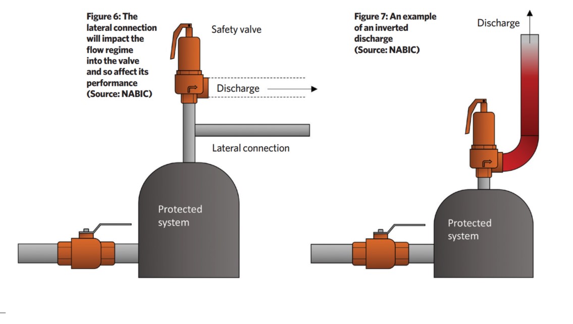
Connection details can adversely affect safety valves. The arrangement of the pipework approaching the inlet of the safety valve – such as fittings, bends and lateral connections (as in Figure 6) – can impact its performance, as streamflow regimes will be affected. On the discharge side of the valve, an inverted outlet (as shown in Figure 6 and Figure 7) will create a backpressure on the safety valve disc, because of the head of fluid in the riser, which will affect the set pressure.
Safety valves should be included in a planned maintenance programme to ensure that the device will continue to operate appropriately, the valve life is prolonged, and that the system operation complies with insurance requirements. Manufacturers will have guidelines on testing and maintenance programmes and procedures. The specific maintenance programme must take heed of the manufacturer’s recommendations, as well as account for the particular conditions of the system and its location.
© Tim Dwyer, 2020.
■ With thanks to NABIC for core material referred to in the production of this article. References on page 68 of CIBSE Journal October 2020.
References
1 The Pressure Equipment (Safety) Regulations 2016 (UK Statutory Instrument 2016 No.1105)
2 The Simple Pressure Vessels (Safety) Regulations 2016 (UK Statutory Instrument 2016 No.1092)
3 Withdrawn Superseded UK standard BS 6759-1 1984 Safety valves. Specification for safety valves for steam and water
4 NABIC recommendation – direct communication
5 Approved Code of Practice and guidance L122 Safety of pressure systems, UK HSE 2014