CPD sponsor
Whether you are streaming a film, using cloud storage or even reading this CPD online, your data is being stored, processed and delivered by a data centre. There are estimated to be around 12,000 data centres currently located around the globe, worth an estimated £180bn, but that value is projected to more than double to £433bn by 2032.1 Driving this surge is the rise of artificial intelligence (AI), which demands far more computing power than traditional applications.
As the global appetite for AI continues to grow, a new era of power-intensive data centres is transforming the industry. Increasing performance demands across central processing units (CPUs), graphics processing units (GPUs), and field-programmable gate arrays (FPGAs) has resulted in substantial increases in device power consumption – commonly referred to as socket power.
While a modern CPU might draw more than 300W, a high-end GPU used in AI and HPC can draw more than 700W, with future models expected to exceed 1,000W within the next year,2 all leading to higher thermal power densities in server racks and a corresponding increase in cooling requirements.
Cooling is estimated to account for somewhere between 20% and 50% of a data centre’s total energy use.3 As the global appetite for digital technologies continues to grow, data centres are under increasing pressure to deliver more computing power with less environmental impact. One advancement supporting this evolution is liquid cooling – a technology that, while not new, has emerged as a solution that offers several efficiency advantages over air cooling.
Limitations of air cooling for racks
The effectiveness of a cooling solution is quantified by thermal resistance, defined as the temperature difference between the processor case and the cooling medium, divided by device power (°C/W). Lower thermal resistance values correspond to more efficient heat removal.4
According to ASHRAE, analysis of manufacturer data shows that maximum socket power has steadily risen, while the thermal resistance necessary to maintain safe device temperatures has declined, so the demand for more effective cooling is increasing. This inverse relationship highlights the escalating demand for advanced cooling strategies either through reduced inlet fluid temperatures or adoption of new technologies.
ASHRAE environmental classes for data centre cooling
ASHRAE Technical Committee (TC) 9.9 defines three complementary classification systems that guide the design and operation of liquid- and air-cooled data centres: water quality classes, water temperature classes, and surface temperature classes. Together, these classes provide a unified envelope for safe, efficient and reliable data centre cooling.
Water quality classes (W1–W4) specify the chemical purity required for liquid cooling loops. W1 demands ultra-pure water for direct-to-chip applications, while W2 allows controlled impurities. W3 and W4 correspond to facility water loops with less stringent treatment, typically separated from IT by heat exchangers.
Water temperature classes (W17, W27, W32, W40, W45, W+) define supply temperatures for facility water. The numbers in the class names (for example, ‘17’ in W17) actually refer to the maximum allowable supply fluid temperature in degrees Celsius. For example, the W27 class specifies that the fluid supplied to the IT equipment must be at or below 27°C. The warmer the temperature the less mechanical cooling required, and the greater the potential for free-cooling and opportunities for waste-heat reuse in district heating, for example.
Surface temperature classes (S1–S3) address condensation risk. They define the permissible relationship between surface temperature and local dew point to prevent moisture accumulation on IT equipment. S1 enforces strict margins, while S3 allows operation in more humid conditions with tolerant equipment.
Air cooling has long served as the standard for data centre thermal management. However, it is increasingly constrained by physical, economic and operational limits. Conventional air systems can support rack densities up to approximately 25–30kW,5 but emerging workloads frequently exceed 100kW per rack.
Fundamentally, air is less effective than liquids at transferring heat. Liquids have significantly higher specific heat capacities and densities than air, which makes them far superior at heat transfer. For example, water’s volumetric heat capacity is more than 3,400 times greater than that of air. This inherent inefficiency means that air cooling is struggling to keep pace with the increasing heat generated by modern IT equipment
Where air is used, more space is needed for air circulation and increased numbers of air cooling systems, such as computer room air conditioning (CRAC) and computer room air handlers (CRAH).
To compensate for higher heat loads, servers relying on air cooling need more airflow, causing fan power to rise, potentially reaching 10% to 20% of server power for denser servers, accompanied by a significant increase in noise.4 Additional constraints from using air for cooling include increased water consumption in evaporative cooling systems, decreased uninterruptible power supply (UPS) capacity as a result of the increased fan power, and limited potential for heat recovery and reuse.
Collectively, these challenges demonstrate that air cooling may no longer be the best option for high-density, high-power IT equipment, accelerating the transition toward liquid-based thermal management solutions in data centres.
The rise of liquid cooling for racks:
Liquid cooling, previously reserved for niche applications such as mainframes and supercomputers, is now emerging as an efficient solution for modern data centres. There are three primary scalable approaches to liquid cooling: direct-to-chip, immersion, and rear-door heat exchangers.
- Direct-to-chip cooling
Also known as cold-plate or direct-liquid cooling, this method attaches cold plates directly to high-heat components such as CPUs. A coolant – typically water, a refrigerant, or a water/propylene glycol mix – flows through micro-tubes in the plates, absorbing heat at source. The warmed liquid is then circulated to a coolant distribution unit (CDU), where it is cooled and recirculated via a closed loop. Single-phase and two-phase direct-to-chip cooling solutions are available, with two-phase solutions using a refrigerant that is boiled by the heat-generating component, turning it into vapour, leveraging the latent heat of evaporation and offering higher efficiency but increased complexity.
Direct-to-chip cooling allows for highly efficient and targeted heat transfer from specific high-power components. It uses smaller volumes of coolant compared with immersion cooling and offers easier accessibility to components for maintenance. However, it may still require some traditional air cooling for non-liquid-cooled components such as power supplies and hard drives.
- Immersion cooling
In this approach, entire servers – including processors, GPUs, and other components – are submerged directly into a non-conductive dielectric fluid, eliminating reliance on air for heat transfer. The fluid directly surrounds and contacts the components, allowing for rapid and efficient heat transfer from the hardware to the liquid coolant. The components and fluid are typically encased in a sealed container to prevent leakage.
In single-phase immersion, the coolant is maintained in liquid form, pumping it through external heat exchangers before returning it to the tank. Two-phase immersion employs low-boiling-point coolants that boil and vaporise upon contact with hot components. The vapour condenses on coils within the chamber, releasing heat to secondary cooling systems before cycling back.
Immersion cooling provides highly uniform and efficient thermal performance, reduces fan and heating, ventilation and air conditioning (HVAC) requirements, and isolates equipment from environmental contaminants. Two-phase designs can achieve two to three times the efficiency of single-phase approaches but raise costs, maintenance demands, and require environmental consideration where fluorinated refrigerants are used.
- Rear-door heat exchangers
A more incremental approach to liquid cooling involves replacing a server rack’s rear door with a liquid-cooled heat exchanger. Warm exhaust air from server fans passes through the exchanger, where circulating coolant absorbs and transfers the heat away. While less direct than chip or immersion cooling, this method integrates readily into existing air-cooled environments, offering a pathway for gradual upgrades of existing data centres.
Hybrid approach
While liquid cooling represents a transformative leap in thermal management, it is not a wholesale replacement for air-based systems… yet. Instead, a hybrid approach is becoming common. Many data centre operators are deploying a mix of cooling strategies based on workload demands, with liquid cooling handling high-density or GPU-intensive racks and air cooling supporting more conventional equipment. This approach balances performance, efficiency, and cost.
These integrated systems can be dynamically controlled via smart building management systems (BMSs) and software platforms, enabling real-time adjustment of CDU flowrates (see below), chiller output, and airflow. This level of orchestration can be efficient and help operators to reduce their power usage effectiveness (PUE) to around 1.2, with some aiming for even more ambitious figures.6
Coolant distribution units
There are two main fluid loops in a data centre liquid-cooling system: the technology cooling system (TCS), sometimes called the secondary flow network, and the facility water supply (FWS), or primary coolant loop.
The FWS is connected to the condensed water system, where heat is rejected to the environment through cooling towers or dry coolers, for example.
The TCS is the secondary loop that circulates coolant to the IT equipment. A 75% water, 25% propylene glycol (PG25) mixture is commonly used (or sometimes ethylene glycol) for the SFN coolant. Heat from the TCS is transferred to the FWS via a coolant distribution unit (CDU).
CDUs are critical components that manage the flow of liquid coolant; they provide cool fluid to server manifolds, receive warmed fluid, and cool this fluid using internal heat exchangers, which usually reject heat to the FWS.
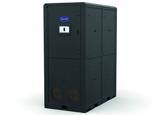
Figure 1: A coolant distribution unit (CDU) from manufacturer Carrier
Rack-mounted CDUs are typically used to provide a TCS loop for a single rack. Free-standing CDUs generally provide the TCS loop for clusters of racks, and are usually located near the racks or immersion tanks.
The performance of heat exchangers or coils determines the CDU’s ability to dissipate heat from the TCS. An important metric is approach temperature, which is the temperature difference between the TCS and the supply fluid provided by the FWS. The lower the approach temperature at a given heat load, the better the cooling efficiency of a CDU.
CDUs must also ensure coolant temperature remains above the dew point to prevent condensation, and serve to hydraulically decouple the FWS from the TCS, which is essential where water quality requirements are different for each loop – see boxout, ‘ASHRAE environmental classes for data centre cooling’.
Benefits of liquid cooling for data centre design
Liquid cooling eliminates the need for large air cooling units and fans, resulting in a smaller physical footprint. This, coupled with the ability of liquid cooling to support higher densities, allows for a reduced data centre footprint for the same IT equipment load, improving space utilisation and potentially lowering building costs. The absence of cooling fans and reduced airflow can also significantly reduce noise levels both inside and outside the facility.
Liquid cooling also minimises the facility’s reliance on energy-intensive air conditioning. Designing for higher facility water temperatures enabled by liquid cooling means less reliance on energy-intensive chillers for mechanical cooling, allowing for more efficient heat rejection using dry coolers or cooling towers.
Rather than rejecting the heat to atmosphere, another option is to recover it. The warm liquid exiting chipsets at, for example, 30°C can be further heated (possibly with a heat pump) and used for district heating networks, industrial applications, or absorption chillers. Research indicates that more than 97% of data centre waste heat is theoretically utilisable. Designs that incorporate this can significantly reduce overall energy waste and improve PUE (see boxout).7
What are PUE and WUE?
Power usage effectiveness (PUE) is a widely used metric for measuring the energy efficiency of a data centre. It is calculated as the ratio of the total facility energy use to the energy used directly by the IT equipment. The theoretical ideal is 1.0, where all energy goes directly to computing. Most traditional data centres operate with PUE values around 1.6, while advanced liquid-cooled facilities are now hitting values in the 1.05 to 1.15 range.
Water usage effectiveness (WUE) is the metric used to measure how effectively a data centre uses water in its operations. It is the ratio annual water consumption to the total annual energy used by IT equipment. Typical WUE for historic data centres is around 1.5litres/kWh, while modern liquid-cooled data centres can have a WUE of 0.1litres/kWh or less.
Liquid cooling also uses less water than many air cooling systems and contributes to lower carbon emissions – aligning with sustainability initiatives and stringent environmental regulations, particularly in Europe. The EU currently has mandatory EU-wide reporting for data centres with an IT load greater than 500kW, which includes water use effectiveness (WUE) to measure how efficiently a facility uses water in delivering IT services. Minimum performance standards are expected by the end of 2026, as part of a broader water-resilience package.8
The UK currently has no specific restriction on data centre water use, but operators are regulated through general regimes that effectively limit water use in water-stressed areas. Broader UK water-resource reforms and drought-resilience measures will probably raise the bar, increasing the need for water-free or closed-loop cooling.
For the electrical installation, rack density increases facilitated by liquid cooling will enable new designs to benefit from higher voltage distribution, such as 480V to server cabinets. This will reduce conductor sizes and numbers of power distribution units, potentially leading to a reduction in electrical installation costs.
Retrofitting
Liquid cooling can be retrofitted into an existing data centre. To do so, however, designers must address a unique set of challenges and considerations that go beyond those for a new build, because many older data centres were designed to keep water away from IT racks to avoid damage from potential leaks. This may require changes to service level agreements (SLAs) where these might explicitly exclude water from the proximity of racks in environments such as colocation facilities.
Adaptations revolve around the need to integrate new liquid-cooling infrastructure with existing power, space, and cooling systems, while also managing costs, operational changes, and maintaining reliability and sustainability.
A hybrid approach, perhaps using rear-door heat exchangers and/or direct-to-chip, is often regarded as a practical strategy for existing facilities. This enables liquid cooling to be used for high-density, GPU-intensive racks, while existing air cooling is used for more conventional equipment to help balance upfront costs with efficiency gains.
While a major benefit of liquid cooling is a reduction in the need for bulky air handling units (AHUs), retrofits will require space for coolant distribution units, manifolds, and piping close to the servers. Coolant quality, too, may need to be upgraded for the TCS circuits, the quality of which may differ from that of the existing FWS.
Finally, new skill sets will be required for those operating and maintaining the upgraded facility, because liquid cooling will demand a new mindset and new ways of working.
Cost considerations
Liquid-cooling systems often have a higher upfront cost because of specialised infrastructure such as CDUs, cold plates and immersion tanks. However, studies suggest that for high-density racks, the initial capital investment (capex) can be comparable with advanced air-cooling solutions.
However, liquid cooling can significantly reduce operational costs (opex) by lowering energy consumption compared with air cooling. It also reduces fan power consumption, and can lead to longer hardware lifespan as the result of lower thermal stress.
There are also longer-term savings: the increased rack density enabled by liquid cooling allows for better space utilisation, potentially reducing the required building footprint and associated costs. Waste heat can be more easily reused, which can further enhance long-term savings.
Current and future take-up
Direct-to-chip cooling has gained traction faster and is more prominent currently than immersion cooling. This is because direct-to-chip systems can be retrofitted into existing air-cooled data centres with relatively modest infrastructure changes. They can operate alongside traditional CRAC/CRAH units and do not require wholesale redesign of facilities.
Direct-to-chip can provide some operational familiarity. Only targeted components (CPUs, GPUs, and so on) are liquid-cooled, while the rest of the system remains accessible to technicians. In addition, major hardware vendors, such as Dell, HPE, Lenovo and so on, now offer servers with built-in cold-plate solutions.
This standardisation makes procurement and servicing straightforward, whereas immersion cooling often requires custom-designed hardware and tanks.
Direct-to-chip is also considered less risky because coolant is confined to controlled loops within cold plates and CDUs, reducing concerns about leaks. Immersion, by contrast, involves higher capital costs, fluid management complexities, and uncertain long-term vendor ecosystems.
Rear-door heat exchangers do not cool components as directly or efficiently as direct-to-chip or immersion, but they are ideal for legacy facilities seeking incremental improvements. In many deployments, rear-door heat exchangers are combined with direct-to-chip to achieve balanced efficiency.
A recent survey indicates that 22% of data centres currently utilise direct liquid cooling, with an additional 61% considering its adoption.9
Over the next five to 10 years, direct-to-chip cooling is expected to remain the dominant technology for new deployments because of its maturity, manufacturer support, and balance of efficiency and serviceability. While rear-door heat exchangers will continue to play a complementary role in retrofits, to extend the life of legacy air-cooled data centres, and hybrid environments.
Longer term, with rack power densities expected to push beyond 100kW, immersion cooling will become increasingly attractive, particularly two-phase immersion with its unmatched efficiency – although challenges around cost, standardisation, maintainability, operator familiarity and coolant sustainability will need to be addressed.
© Andy Pearson, 2025.
References:
4 ASHRAE: Emergence and Expansion of Liquid Cooling in Mainstream Data Centers White Paper Developed by ASHRAE Technical Committee 9.9, Mission Critical Facilities, Data Centers, Technology Spaces, and Electronic Equipment.
6 Carrier: The Rise of Liquid Cooling in Data Centres – Carrier supplied paper <<NEEDS link>>