
CPD sponsor
Fan coil units (FCUs) are a widely adopted solution for providing heating and cooling in commercial buildings, such as offices and hotels. In the UK, FCUs first became popular in the mid-1970s, when the majority of commercial heating systems were based on gas-fired boilers connected to low-pressure hot water (LPHW) heating circuits running at 82oC flow/71oC return.
More recently, the growth in the use of electric heat pumps and the expected future growth in low-temperature heat networks means that LPHW systems often now run at much lower temperatures, often 45oC flow/40oC return. This CPD will outline the basic design considerations when using FCUs with a lower-temperature heating system.
FCUs condition the air in a building using a water-to-air heat exchanger and a fan. The fan draws air across the heat exchanger, which is served by either low-temperature hot water or chilled water at any one time. This either heats or cools the air before it is supplied to the room.
FCUs are sometimes used in conjunction with a central air handling unit to supply conditioned outdoor air for ventilation, with the FCU recirculating and further conditioning the room air. The FCU’s function – that is, cooling or heating and, possibly, ventilation – is controlled to meet the thermal demands of the area being supplied. This makes them particularly suited to commercial office applications, where different areas may have varying occupancy and load requirements.
Various configurations of FCU are available, including: horizontal units designed to be concealed in ceiling voids; horizontal units intended to remain exposed for a more industrial aesthetic; horizontal units for installation beneath raised floors; and vertical units (either concealed or exposed), which are suitable for refurbishments and spaces with low floor-to-ceiling heights.
Whether for new build or retrofit, a key benefit of using fan coils is that the energy required to meet the heating and cooling demand is transferred to the conditioned space via water flowing within a pipework system.1 This medium requires significantly less space and transport energy than would be the case if the same amount of heating or cooling was being transferred using air.
Heat exchanger
FCU heat exchangers are typically formed from a coil of copper pipe that passes backwards and forwards through the airflow. The pipework forms the primary heat transfer surface. The copper tube is then expanded onto aluminium fins, which form the secondary heat-transfer surfaces. The fins increase the surface area over which heat can be transferred to the air.
FCUs can be either 2-pipe or 4-pipe systems.
- A 2-pipe fan coil has a single heat exchanger coil that can provide either heating or cooling at any one time. Such systems often incorporate a changeover to switch the supply for the entire building or zone from heating mode to cooling mode, or vice versa. Changeover is typically manual (for example, in autumn and spring), so unusual weather patterns might make the point of changeover difficult to determine.
- A 4-pipe system has two separate coils – one dedicated to heating and one to cooling, allowing both services to be available concurrently. This system is common in the UK because of variable weather patterns (see Figure 1).
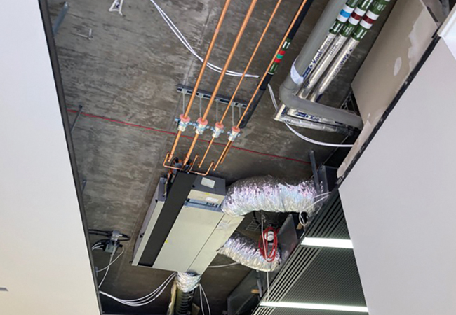
Figure 1: A 4-pipe horizontal FCU concealed in the ceiling void (Source: Ability Projects)
Practically, the copper coils of both coils are often housed in the same single-block heat exchanger, where they can share the aluminium heat-transfer fins to make the unit more compact. Only one of the coils would be active at any one time, with a narrow control ‘dead band’ between the modes, where neither the heating nor cooling coil is active.
While the primary purpose of a FCU is to provide cooling, it can also provide heating. Heat is required when ambient temperatures drop below the desired comfort level for the space, typically during the winter. FCUs can also be used to preheat a space prior to occupancy.
In the past, the heating medium was provided by a gas- or oil-fired boiler. A more recent development is the use of electric heat pumps and low-temperature heat networks to provide low carbon heat.
Growth in low-temperature heat sources
The primary driver behind the growth of low carbon heat sources is the UK’s commitment to achieving net zero emissions by 2050. This goal necessitates a significant shift away from fossil fuel-based heating systems, such as gas- and oil-fired boilers, and a shift towards the use of electric heat pumps and low-temperature heat networks.
Take-up of heat pumps is also being driven by businesses looking to future-proof their heating, to reduce their carbon footprint and, potentially, their energy bill.
Historically, heating systems in commercial buildings were designed to operate at a temperature of 82oC flow and 71oC return, with a temperature differential (Δ T) of 11K. Generally, air source heat pumps using common refrigerants produce water at a maximum temperature of between 55oC and 60oC at -5oC ambient temperature.2 However, as the technology continues to evolve, output temperatures are increasing, with the use of CO2 and R290 (propane) refrigerants, for example.
The availability of low carbon heat for the built environment will increase with the introduction of heat network zoning, expected later this year following the introduction of the Energy Act 2023.3 A heat network usually comprises the flow and return pipes that convey heat from a heat source (usually an energy centre) to the customers, and can include both communal and district heating. The Act mandates that certain existing buildings and low carbon heat sources within a designated zone connect to a local low-temperature network.
To ensure heat networks meet a minimum level of performance and reliability, a Heat Network Technical Assurance Scheme4 is scheduled to launch in 2026. This builds on CIBSE’s Code of Practice CP1, which aims to ensure that heat networks meet a minimum level of performance and reliability.
CP1 is focused on third-generation heat networks, typically fuelled by gas combined heat and power engines or boilers. These supply heat at 90-60oC with a return temperature at around 50-40oC. In the future, district and community heating is expected to move towards lower carbon, lower-temperature heat networks in order to use a higher contribution from renewable energy and waste heat.
The code of practice describes low-temperature fourth-generation heat networks as supplying heat at around 60-45oC, with a wider Δ T and return temperatures at around 30-15oC. Similarly, it describes ultra-low-temperature fifth-generation systems as those supplying at <45oC, with return temperatures at around 25-15oC.5
Case study: One Glass Wharf
At One Glass Wharf in Bristol, the heating system was upgraded by replacing an 82/71°C boiler-fed system with a 45/35°C heat pump system. The change aimed to reduce carbon emissions and improve efficiency. To enable effective operation at the lower water temperatures, the existing FCUs were replaced with Ability Evo FCUs, incorporating low-temperature heating coils. These were specifically designed to deliver the required comfort levels without the need to increase fan size, airflow or noise levels.
Testing confirmed that cooling performance was maintained. The switch to smaller FCUs designed for low-temperature operation reduced embodied carbon by 6.2%, as verified using the TM65 methodology, compared with larger conventional units. Electrical consumption was reduced by 24% by lowering the air volume requirements, and the air volume was cut by 18% with no loss of cooling output or acoustic performance.
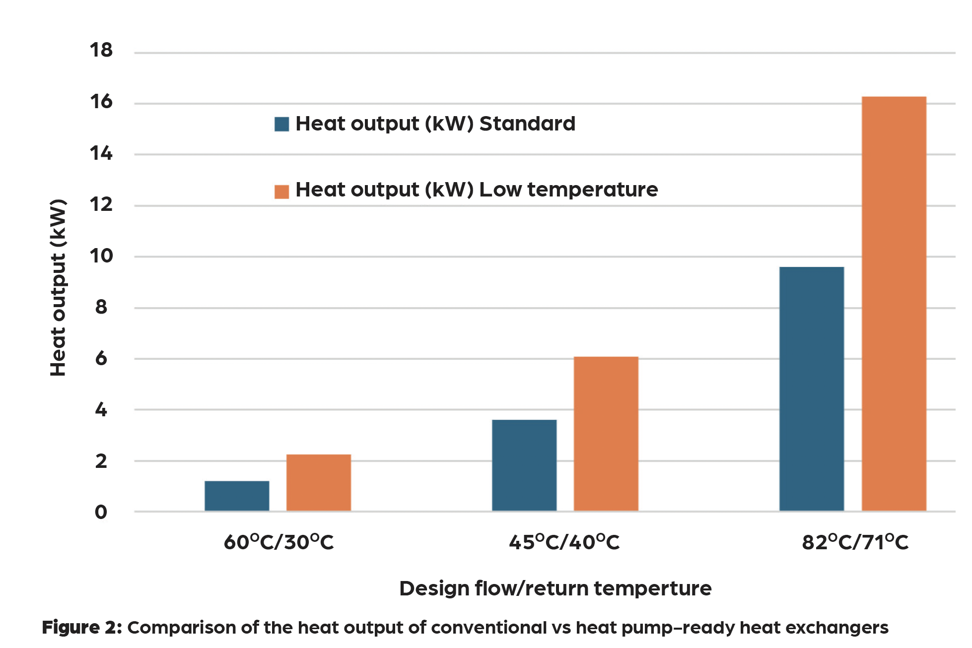
Further testing showed that the new units provided up to 150% more heating capacity at 60/30°C and 108% more at 45/40°C, without reducing cooling performance. Pressure drops were reduced by up to 80%, lowering system resistance and pump energy demand, compared with typical conventional fan coils. The specific fan power was measured at 0.15W.L-1.s-1, compared with 0.16W.L-1.s-1 for larger traditional fan coils in low-temperature applications.
This project shows that low-temperature heat pump systems can be successfully integrated into existing commercial buildings without compromising comfort or acoustic performance. It also indicates that careful selection of terminal units for low-temperature operation can deliver embodied and operational carbon savings, alongside improved heating capacity and reduced pumping energy.
Impact on FCU heating performance
The move away from fossil fuels to electric heat pumps and low-temperature heat networks is likely to lead to a reduction in the overall temperature of heating systems. This demands that internal heating systems, such as FCUs, operate effectively with much lower emitter temperatures.
Typical heating system flow and return temperatures could be as low as 45oC and 40oC, respectively. At this lower system temperature and reduced temperature differential, the heat output from a FCU heating coil will be significantly less.
To compensate for the FCU’s reduced heat output, a design could incorporate a greater number of FCUs or it could use much larger FCUs. An alternative solution would be to use an FCU with a heat exchanger designed specifically for use with low-temperature heating circuits.
Heat pump-ready FCUs
To address the need for an increased heat output from a standard FCU, some manufacturers are now producing FCUs that incorporate heat pump-ready heat exchangers.
To enhance the heat output from a heat exchanger, the number of dedicated heating tubes in the heat exchanger coil are increased. For example, a conventional coil of 36 tubes might have only had four dedicated to heating, while a heat pump-ready heat exchanger might feature more heating tubes to increase the coil surface area by 50% or more.
Adding to the number of heating tubes will increase the heat exchanger’s surface area, which will increase the unit’s heat output from lower-temperature inputs, without the need to increase the volume of air passing over the coil. This should ensure the size of the FCU and its acoustic performance remain broadly similar.
Impact on heating performance
Heat pump-ready heating coils can provide significantly enhanced heating capacity at lower system temperatures compared with traditional coils (as illustrated in Figure 2).
It is important to ensure that any enhancements to the heat exchanger heat output are not at the expense of the unit’s cooling performance.
Increasing the number of passes in a heat exchanger block, however, has the potential to increase the hydraulic pressure drop across the heating coil, increasing pump energy. With careful design, using an increased number of heating tubes and a contraflow setup, it is possible to design the coil to ensure no increase in system hydraulic resistance and no increase in pump energy. The corresponding lower pump-energy usage can result in reductions in system electrical consumption by up to 24%, compared with a traditional FCU used with a low-temperature heating circuit.
In addition to enhanced hydraulic efficiency, it is possible, with careful coil design, to maintain a similar airflow pressure drop across the coil.
FCU controls
The control of heat pump-ready FCUs is typically achieved by first adjusting the heating or chilled water flowrate through the heat exchanger (water-side control), then by adjusting the airflow through, by altering the fan speed (air-side control).
An increasing number of FCUs are now fitted with electronic pressure-independent valves (EPIVs) for water-side control. Unlike traditional pressure-independent control valves (PICVs), which suffer from hysteresis, EPIVs use ultrasonic flow meters and intelligent actuators to continuously modulate water flow, and do not suffer from hysteresis.
EPIVs can operate at much lower pressures (typically 15 to 1kPa) compared with PICVs, which usually require a minimum differential pressure of 30kPa to operate. The fine control available from an EPIV can be integrated into a building management system (BMS), reducing system pressure requirements and, consequently, the pump energy consumption for the entire system.
Modern FCUs typically use electronically commutated DC fan motors, which are significantly more efficient than older motors, particularly at reduced fan speeds. The motors also make it simple to control the fan speed. Fan speed turndown in FCUs is typically limited to no lower than 70% of design speed, to maintain effective air distribution patterns and avoid issues such as the ‘dumping’ of cold air onto room occupants.
BMS integration
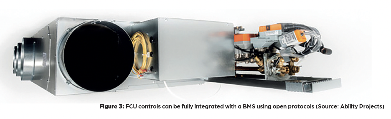
FCU controls can be fully integrated with a BMS, often using open protocols such as Modbus and BACnet,6 enabling controls equipment from different manufacturers to work with each other (see Figure 3). This allows for centralised management of global functions, such as time schedules and optimum start/stop, and enables remote monitoring and control.
The BMS can incorporate weather compensation and learning capabilities to optimise preheating/cooling periods, regardless of whether the heat source is traditional or low-temperature – although lower-temperature heating systems may need a slightly longer preheat period.
Commissioning a FCU involves verifying the communication and data exchange between the FCUs and the BMS, ensuring that the pre-programmed control logic for both heating and cooling functions is set correctly, and that desired set points are achieved efficiently. This also includes checking the ‘dead band’ settings to prevent simultaneous heating and cooling, which would waste energy.
Future-proofing considerations
FCUs specifically designated ‘heat pump-ready’ are particularly suited for use on higher-temperature applications where a gas-fired boiler is currently in use to supply heat, but where the boiler is expected to be replaced by a heat pump in the future. The unit’s ability to achieve the required heating outputs without requiring replacement or significant reconfiguration will help reduce project costs, minimise rework and combat waste.
The development of heat pump-ready FCUs will support the move away from fossil-fuel boilers towards heat pumps, thereby contributing to the UK’s net zero ambitions. It also allows for future-proofing building designs, enabling a smooth transition to heat pumps later, without needing to replace or reconfigure existing FCUs, which saves costs and supports sustainability objectives.
© Andy Pearson, 2025.
References:
2CIBSE AM17 Heat Pump installations for large non-domestic buildings, CIBSE 2022.
5CIBSE Heat Networks: Code of Practice for the UK, CP1 CIBSE 2020.
6 CIBSE TM43 Fan Coil Units, CIBSE 2008.