
This article outlines the factors that drive the need for water treatment in closed-loop water systems and focuses on the processes that provide ‘chemical-free’ water treatments. It also explores how such systems provide treatment of closed-loop water systems, such as those used in heating and cooling systems for buildings.
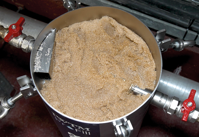
Water treatment is typically undertaken at the pre-commissioning stage and as an ongoing process to establish and maintain water quality. This ensures that the circulating water does not become contaminated with particulate matter, bacteria or other harmful substances (such as shown in Figure 1), which can lead to system failure.
As discussed in the comprehensive guide BSRIA BG 50,1 appropriate water treatment can help to inhibit corrosion and protect the metal components of the system, so reducing the opportunity for leaks, reductions in efficiency and, ultimately, system failure. It can prevent the formation of scale on the inside of pipes, fittings and heat exchangers that will otherwise reduce the efficiency of the system and reduce system reliability. Appropriate water treatment can also control microbial growth, helping to prevent bacteria and other microorganisms that can grow in closed systems, causing problems such as corrosion and fouling.
Monitoring and controlling the water quality across the life of the installation will improve system performance, lower energy costs, reduce the need for repairs and maintenance, and potentially extend the life of the system.
There are several parameters that will impact the water quality in closed-loop systems. Oxygen dissolved in the water acts as a powerful oxidising agent, readily interacting with metals and accelerating corrosion processes. Dissolved oxygen may be minimised through proper system design, degasification, and by maintaining a closed loop with minimal air ingress.
Total dissolved solids (TDS) – an amalgam of minerals, ions, and other dissolved substances in the water – will increase the water’s electrical conductivity and impact the rate of scale accumulation and corrosion. Water ‘hardness’ is specifically identified as the amount of calcium and magnesium salts in water, generally in the form of bicarbonates, chlorides and sulphates that, if left, will accumulate as insoluble carbonate (scale) in water systems. Chloride ions are notorious for promoting localised corrosion, as they can penetrate and destabilise the naturally forming protective oxide layer, leaving the underlying metal vulnerable to corrosion.
The acidity or alkalinity of the water, as measured by the pH, significantly influences corrosion rates. Generally, lower pH (more acidic) environments increase corrosion, as this dissolves the protective oxide layer on the surface of metals, leaving the underlying metal exposed and vulnerable to corrosion.
Figure 1: A 40μm filter basket from a reaction tank (as in Figure 3) that was removed shortly after installation into a new-build system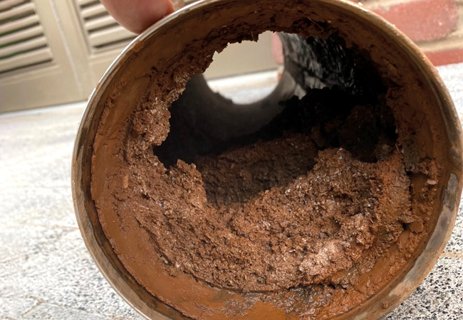
Conversely, slightly alkaline environments can help thicken the protective oxide layer, offering better protection – although excessively high pH can induce other degradation processes (such as disrupting the passivity of stainless-steel components).
Higher pH will tend to reduce most bacterial growth. However, the bacteriological quality of the water will be highly dependent on the cleanliness of the initial system and the fill water.
These factors interact and influence each other, so a holistic approach – considering all relevant parameters and implementing a customised treatment plan based on a specific system and water characteristics – is key to minimising corrosion risk and ensuring the longevity of a closed-loop system.
There are several methods that are used to treat water for closed-loop systems either for continuous use, or to treat fill or make-up water, that may be applied individually or in conjunction with others, depending on the specific system requirements. Physical methods are often used to remove impurities from the water.
This may be through some form of filtration to remove particulate matter, by deaeration methods that reduce dissolved and partially dissolved gases; and employing techniques such as reverse osmosis, which forces water through a semipermeable membrane that has microscopic pores to allow water molecules – but not most contaminants – to pass through.
Resin-based demineralisation units (or cartridges), strainers, softeners and clarifiers are employed to remove impurities from the water.
In the UK, chemical water treatment is currently the most common type of water treatment for closed systems, where chemicals are added to the water to inhibit corrosion, prevent scale formation, and kill bacteria. However, chemical-free is becoming increasingly popular – a method of water treatment for closed-loop hydronic systems that does not use inhibitors or biocides.
The method employs an initial fill of demineralised, clean water, and then electrochemistry is used to control the causal elements of scale and corrosion – minerals, salts, oxygen and other gasses. In recent years, this method has increased in popularity; it also meets the requirements of Germany’s influential guideline VDI 20352 .
VDI 20352 Part 1: Prevention of damage in water heating installations – Scale formation and waterside corrosion is a German guideline that provides extensive commentary and recommendations to prevent scale and corrosion in heating systems. It offers guidance on selecting suitable corrosion-protection methods, including the use of demineralised system water, both for the initial fill and for make-up water, and adjusting water chemistry through pH modification. It explains techniques to minimise scale formation, and for effective demineralisation, deaeration and filtration. The guideline tabulates recommended values of three parameters, which limit the likelihood of damage resulting from scale formation and corrosion. Correctly meeting the provisions that aim to prevent scale and corrosion will also contribute to preventing bacteriological growth, and so also reduce the risk of sludge formation.VDI 2035
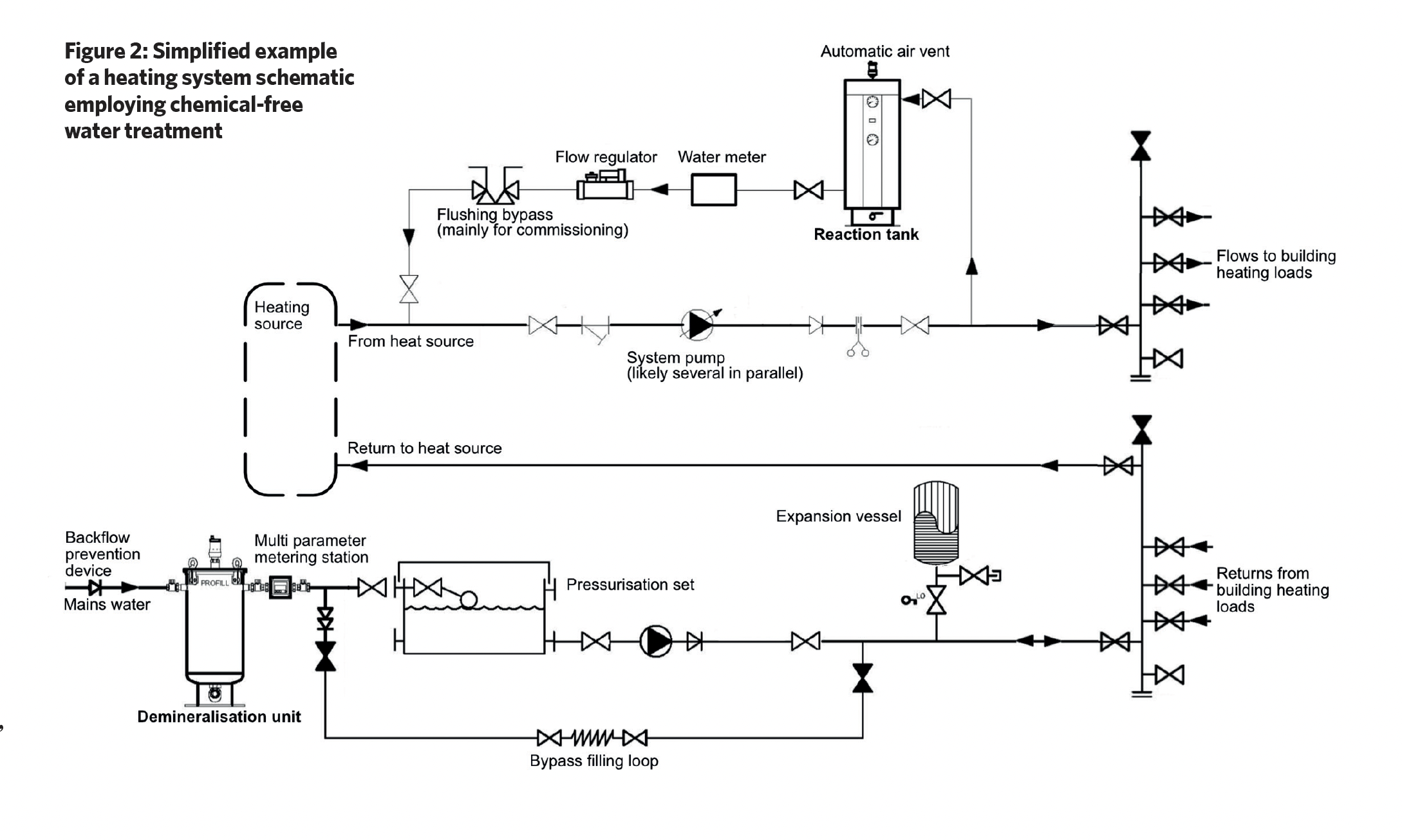
Chemical-free water treatment systems typically consist of a demineralisation unit and a reaction tank, and although this employs chemical and electrochemical processes, it does not add any chemicals to the system water.
As shown in the example system in Figure 2, mains water passes through the demineralisation tank, which contains a mix of cation and anion exchange resins. Cation resins exchange positive ions such as calcium and magnesium ions with sodium ions, and anion resins exchange negative ions and remove dissolved solids, salts and other ions from water, so that the fill water has no, or low, conductivity. The mixed resin also removes carbon dioxide.
Over time, the resin becomes saturated with contaminants, and this will lead to decreasing water quality. Resin capacity is dependent on the hardness of the local water and the total flow through the unit over time. As the resin becomes saturated with mineral ions it needs regeneration or replacement. Regular monitoring of conductivity or specific ion levels helps determine when resins can no longer perform their function. Resin typically has a useful life of three years in a system, when it will then require changing even if it has not become saturated.
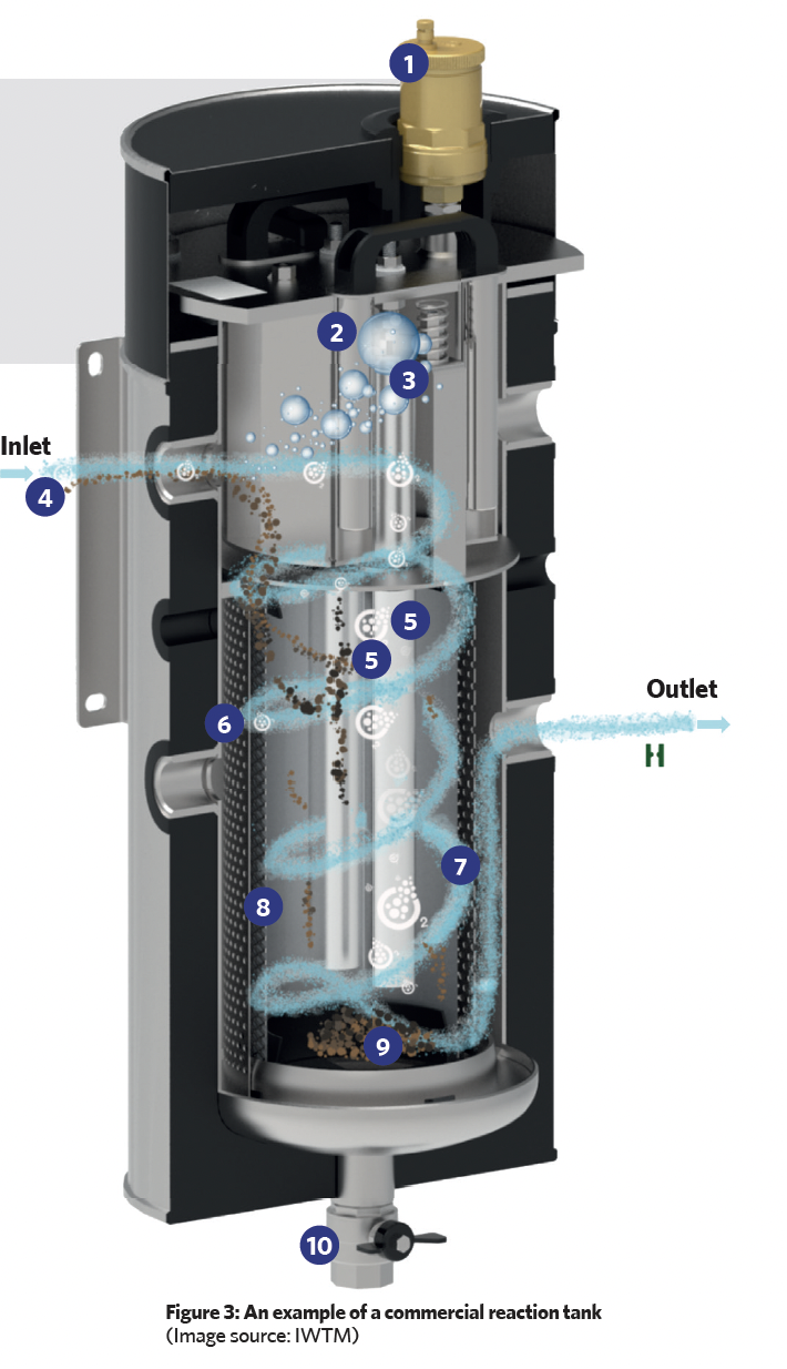
The reaction tank (such as that shown in Figure 3) employs sacrificial magnesium anodes surrounded by a filter and a strainer, which is then contained in a cylindrical stainless-steel housing. The tank is positioned in the system where the water is hottest (for example, near the boiler output – as in Figure 2 – or the input to a chiller), as this is where there will be the greatest number of bubbles of entrained air and gases.
In the illustrated reaction tank, the water enters tangentially, creating a swirling motion, and as a result of centrifugal forces, heavier particulate matter is thrown outwards, which then falls and collects at the base of the unit. The outer cylindrical strainer captures any remaining larger particles while a finer (micron) inner filter removes smaller particles. These particles will be held in the strainer and micron filter, and will drop to the lower chamber when the unit is being ‘blown down’. (During scheduled maintenance, the blow-down valve is briefly opened to force a controlled flow of water back through the filter and strainer screen, in order to force out accumulated debris through the blow-down valve into an appropriate waste-disposal vessel. The valve is then closed.)
This filter also traps micro air and gas bubbles, which then amalgamate and buoyantly rise, to be removed from the system by an automatic air vent. This degassing process is continuous, and when the treated, degassed water leaves the tank, it cools and passes around the distribution system absorbing trapped system air that will, in turn, be removed to atmosphere as the water passes back through the reaction tank.
The magnesium anodes in the tank have significantly more negative electrochemical potential and so are more ‘active’, so they corrode when they are in electrical contact with the stainless-steel outer shell and stainless-steel filter assembly – which act as a cathode – in the presence of an electrolyte (such as the ion containing water).
Reaction key:
1 Automatic air vent 2 Magnet to capture metallic particles 3 Air and other gases rise through buoyancy forces 4 Water enters with entrained particles, dissolved oxygen and air micro bubbles (located at point of hottest system water) 5 Magnesium anodes 6 Strainer to capture larger particles. 7 Approximate water path 8 Micron filter (40μm) basket to remove smaller particles and entrained air – can be swapped for bag filters down to 0.5μm for finer particle filtration 9 Dirt, sludge, debris, and metallic particles (including the magnesium residue from the expiring anodes) collect inside the basket 10 Blow-down valve periodically used to remove accumulated matter
As a result of the electrochemical reaction between the magnesium anodes and the surrounding cathode, magnesium hydroxide is produced (at the anode), and any dissolved oxygen is gradually removed (through a reaction at the stainless-steel) as the water recirculates. Hydroxide ions produced at the cathode increase the pH of the water – a process known as ‘self-alkalisation’.
However, excessive alkalinity can also lead to issues such as scale formation and reduced heat-transfer efficiency, so the pH should be carefully monitored. (The electrochemical reactions also produce chloride and hydrogen gas, which rises to the top of the tank to be released to the atmosphere.)
The cathode and the anodes are connected through a galvanometer that shows the electrical flow between the two. As pure water is non-conducting, more impurities and oxygen in the water will increase the current. As the water quality improves, the current diminishes. The system is self-regulating, as the anode automatically works harder with corrosive water. All the components should be cleaned on a regular maintenance cycle, which will be scheduled depending on the installation.
Reaction tanks are typically sized based on the system heating or cooling load, the system volume, and the system operating temperature. So, for example, chilled water and heat pump systems will typically need a larger unit than a boiler-fed system, as they do not benefit from the higher temperatures to assist the removal of bacteria – this is achieved by a greater surface area of the anodes.
For the initial system fill, a chemical-free installation requires ideal fill water that is bacteria-free with a controlled pH and low conductivity. Typically, the fill will pass through a bacteria filter of 0.5 microns or a reverse osmosis filter (with an appropriate protective pre-filter) to block microbes from entering the system.
The water will then pass through a mixed demineralising resin bed to deliver the required quality fill water. Early operation of the system at its maximum temperature after filling should be carried out to remove gas and air pockets. Once filled, the installation debris is cleared by circulating the system water to velocities as recommended in BSRIA BG 29,3 using a mobile high-flow filtration unit that filters the system water without discarding any water to drain.
As reflected in VDI 2035,2 BSRIA BG50,1 and CIBSE Guide M,4 system performance monitoring is essential for the proper maintenance of closed heating and cooling systems. It can help to identify potential problems early on, prevent costly repairs, and ensure that the system is operating efficiently.
Recommendations in CIBSE CP15 are to continually monitor corrosion in the system water using electronic coupons (that mimic the behaviour of a physical metal coupon to measure corrosion parameters electronically), which, in conjunction with automatic pH and TDS monitoring systems, can feed into building management systems (BMS). Reaction tanks are available with real-time monitoring that can deliver information both locally and directly to a BMS to provide a continuous record of these critical factors.
Despite being widely embraced for many years across Europe, it is only in recent years that chemical-free water treatment for closed-loop systems has been more widely adopted in the UK. It is increasingly being referenced by HVAC manufacturers as being suitable for systems operation, and is being adopted by a growing number of designers and users.
Further reading:
Chapter 12 of CIBSE Guide G provides an excellent foundation for understanding corrosion and corrosion protection.
Annex E of CIBSE CP1 Heat networks: Code of Practice for the UK (2020) provides useful tables of recommended parameter limits for heat networks (closed-loop networks).
References:
- Simpson, P, BSRIA BG 50/2021: Water treatment for closed heating and cooling systems’, BSRIA 2021.
- VDI 2035 – Part 1 : Prevention of damage in water heating installations – Scale formation and waterside corrosion, Verein Deutscher Ingenieure 2021.
- Parsloe, C, and Ronceray, M, BSRIA BG 29/2021 Pre-commission cleaning of pipework systems, BSRIA 2021.
- CIBSE Guide M.
- CIBSE CP1: Heat networks: Code of Practice for the UK, CIBSE 2020.