
As a new tenant takes over a section of a commercial building, whether a new construction or an existing tenanted premises, it is very likely that their specific requirements will require a reconfiguration and refitting of the space to suit their particular needs. This process, known as a ‘fit-out’, can result in significant expense both financially and environmentally, as hardware such as partitions, furnishings, fixings, lighting, IT, and environmental systems that were previously useful assets to the previous tenant are variously altered, removed or replaced.
One common element that contributes to this potentially profligate process is the fan coil unit (FCU). This CPD will consider the fit-out process, and assess some options that may improve the environmental and financial impacts of fitting out commercial buildings to satisfy tenant needs.
AHU or traditional FCU?
An air handling unit (AHU) and a traditional, single-fan or multi-fan FCU will both typically include at least one filter, a cooling coil (with condensate collection and drain), a heating coil (in most FCUs), a single supply fan and access panels to allow servicing. The AHU often incorporates full humidity control, is likely to supply (at least a proportion of) outdoor air, and would typically benefit from heat recovery from extracted vitiated air.
The main difference is that an AHU is a centralised system that can condition air for multiple zones in a building, while a traditional single-fan FCU is a decentralised system that would condition recirculated air to control the temperature for a single zone. FCUs are often used to provide localised single-zone cooling and heating in conjunction with a centralised AHU that supplies tempered outdoor air to, and removes vitiated air from, the zone.
According to the Royal Institution of Chartered Surveyors (RICS),1 around 11% of total construction expenditure in the UK is allocated to fit-outs. RICS suggests that buildings may undergo as many as 30 to 40 fit-outs over their life-cycle. For a new building shell, or one that has been completely refurbished, the Cat A fit-out will typically include essential elements necessary for occupancy but still provide a ‘blank canvas’ ready for the tenant to individualise it.
It would normally encompass elements including basic (infrastructure) electrical, plumbing and mechanical services, raised access flooring, finished wall coverings and suspended ceilings, and encompass the provision of hallways, staircases, lifts, and toilet facilities. Air conditioning may be included during this phase. In the commercial sector, there are several heating, ventilation, and air conditioning (HVAC) solutions available, but FCUs are a common choice because of their ability to offer tenants zoned control over the indoor temperature.
During this stage, open-plan areas are typically extensive and require the selection of large and powerful FCUs to meet the demand for conditioned air. FCUs serving areas near glazing around the building’s perimeter are sized to handle both heating and cooling requirements. In central areas where heat loss is minimal, FCUs are often specified for cooling purposes only.
After the property space has been leased, the Cat B fit-out customises the area to suit the specific needs of the tenants. This involves reconfiguring the interior layout to create working spaces, reception areas, kitchen facilities and meeting rooms. It also includes the installation of all the necessary IT, audio-visual equipment and lighting systems.
These alterations can have an impact on the heating and cooling requirements, and it is common for the original placement of the FCUs from the Cat A fit-out to no longer be optimal for serving the requirements of the new layout. The larger FCUs originally installed may now be inappropriate to condition the air in what is likely to be collection of smaller spaces. Most FCUs are typically selected to operate at about half fan speed to allow some variation above and below to cope with fluctuations in demand.
However, FCUs do not operate most effectively at low speeds, so with prolonged operation at very low speeds (to meet the smaller load) they will not operate with optimum performance.
As a consequence, some of the larger FCUs may be removed during a Cat B fit-out and possibly replaced by smaller FCUs that are better suited to cater to the requirements of the updated layout. These larger FCUs could potentially find use elsewhere in the project but, in many cases, they are no longer needed. The manufacturers typically do not accept these units for return, since they have been previously installed, commissioned, and have already been in operation during the Cat A phase – essentially rendering them second-hand.
Contractors might choose to retain the large FCUs and store them for potential use on other projects; however, it is likely that a significant proportion end up as scrap for metal recycling. The process of removing the original FCUs not only consumes time and money but also generates additional embodied carbon and waste. At the conclusion of the lease period, new tenants may require modifications to the layout, necessitating the repositioning of existing FCUs or the acquisition of new ones to effectively manage the heating or cooling demands of the space.
In certain cases, particularly when disputes between landlords and tenants lead to lease terminations, landlords might insist on restoring the building to its original condition. This typically involves the removal of the FCUs and the installation of new, larger FCUs according to the building owner’s original specifications. However, these larger FCUs might be considered as somewhat temporary and may be replaced when the space is leased again. This cycle further exacerbates carbon emissions and contributes to construction waste.
There are several options that could help prevent this wasteful – and likely repeated – cycle of FCU removal and replacement, as discussed below.
The first option is that the project could bypass the Cat A stage and proceed directly to the Cat B phase. However, this approach demands a high level of collaboration during the design phase, and is only feasible when the ultimate client for the building has been identified. This scenario becomes possible when, for instance, a large corporation makes the decision to both construct and occupy a building or commits to a long-term lease of the property.
While this does occur, it remains uncommon and not without its challenges. The Cat B specification must be fixed relatively early in the project and, consequently, any design modifications necessitated by shifts in the company’s strategy, structure or size can introduce their own set of issues if not carefully managed.
Alternatively, an option is to utilise a greater number of smaller FCUs, offering enhanced inherent flexibility and potentially decreasing the waste generated during removal and replacement that might otherwise be needed. Nevertheless, while this approach could diminish the likelihood of having to revisit the FCU strategy during the Cat B phase, it would lead to increased costs for the building owner while reducing the tenant’s Cat B expenses.
Each smaller FCU would also involve the installation of a controller, valve set, pipework and electrical connections. Increased numbers of FCUs will also add to the complexity of structural coordination when setting out a reduced size zone (or ‘bay’). While the use of smaller FCUs can enhance the property’s appeal and make it more attractive to prospective tenants, the initial cost linked to procuring and installing additional FCUs may pose challenges when justifying this expenditure to the building owner.
A more radical option, for larger multi-floor projects, is to fit-out only some floors as Cat A and fit-out the remainder of the floors to Cat B once tenants are secured. However, a direct Cat B fit out may then require the complete infrastructure pipework, ductwork and wiring to be installed so the tenant may have a longer wait to make proper use of their space. This may deter some clients for whom time is of the essence. However, it is a likely to provide a more sustainable, and potentially cost-effective, approach.
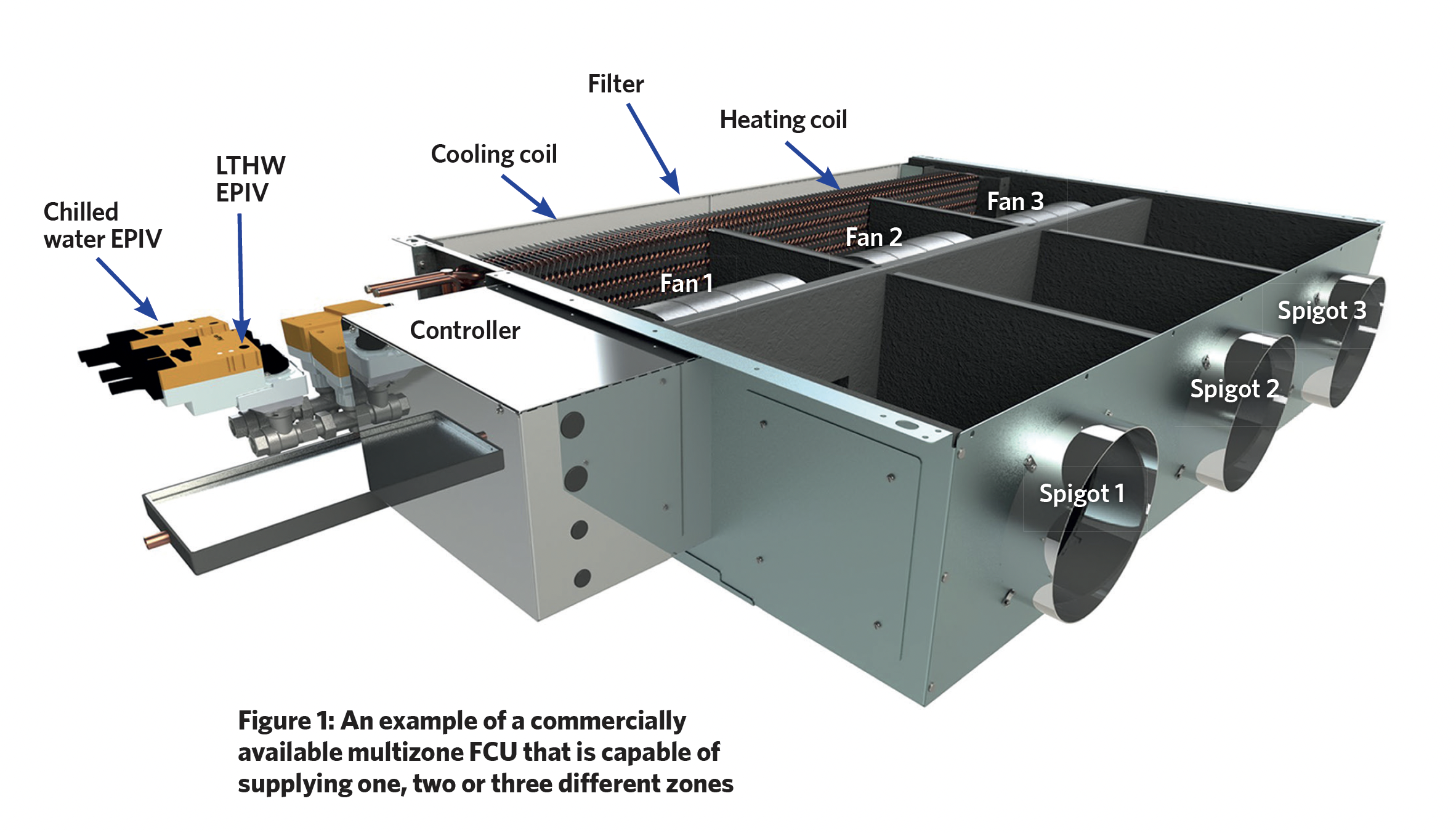
The final option, to be discussed in this article, provides a novel FCU system that can be installed to fully meet the needs of Cat A and then be adapted to allow reuse (with, mainly, ductwork and diffuser alterations) to completely satisfy tenant requirements at Cat B. A ‘multizone’ FCU – which is described more fully below and pictured in Figure 1 – can supply up to five zones, each of which may be operating with different temperature setpoints and have different load profiles. Although similar in external appearance, this is quite different to a traditional single-fan or multi-fan FCU with multiple spigots, as that will offer no opportunity to continuously control the proportion of the total flowrate to the separate outlets.
Multizone FCU
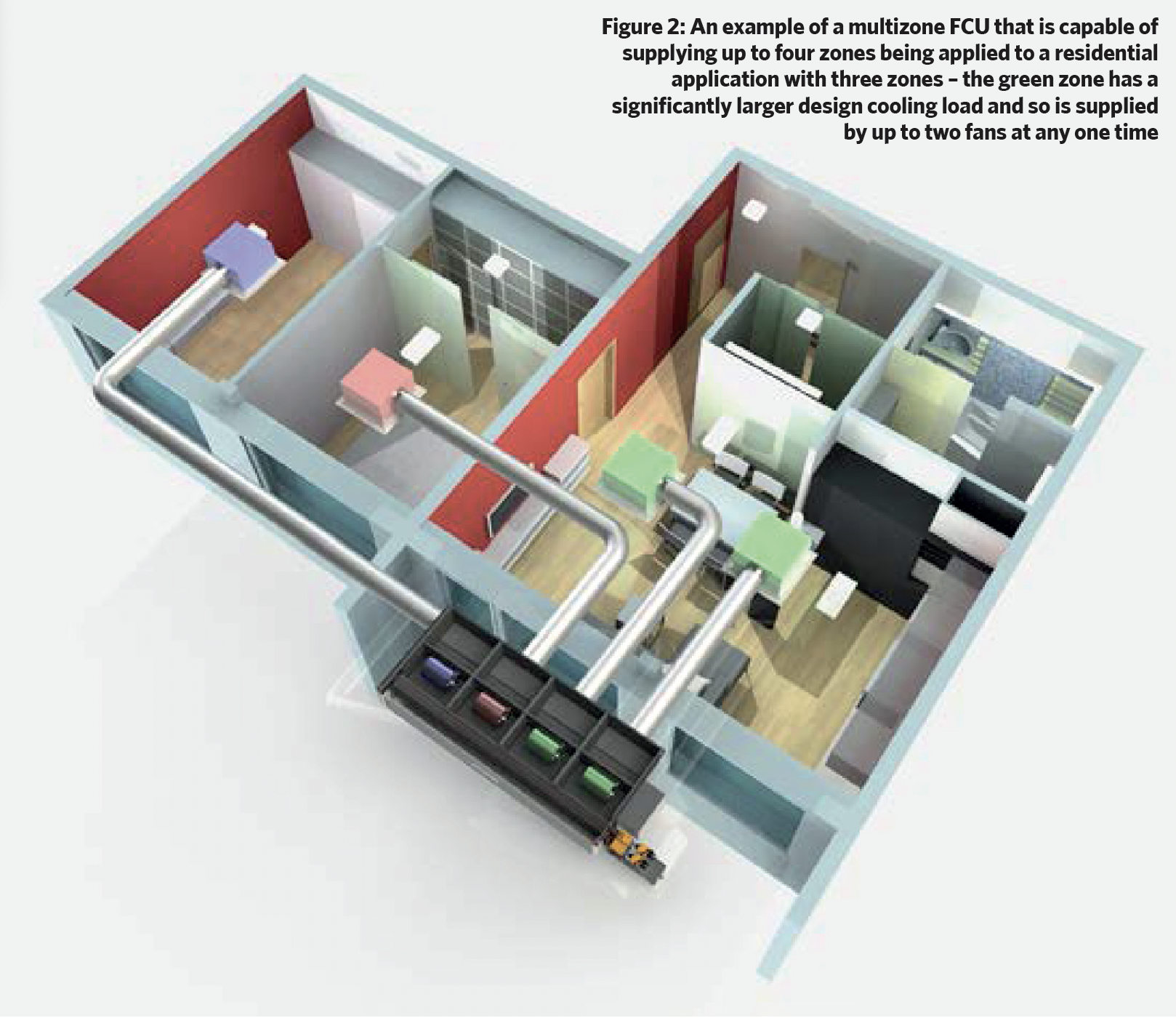
Advances in the design of compact digitally controlled electronically commutated (EC) motor-driven fans enabled the development of a single FCU housing that incorporates multiple, partitioned, independently controlled direct-drive EC fans, which supply separate zones, drawing from a common plenum of treated (cooled/heated) air (as illustrated in Figure 2).
The units typically contain a multi-row cooling coil and a heating coil. The speed of the fans may be individually controlled by the integrated controller that interrogates all the separate zone temperature sensors and assigns a priority zone. This will be the zone that is furthest from its set-point and, for example, could require cooling. With the multizone FCU unit in cooling mode, the priority space receives the full design air volume flowrate, with other cooling zones receiving proportionately the air flowrate they need to satisfy their lower cooling requirements. Any space that requires heating at that time has its fan stopped and no air is delivered. Once the cooling demands have been satisfied, and if there is still a need for heating, then the cooling coil valve closes and after a purge period the cooling zones fans stop. The heating coil valve is opened and the heating zone(s) fans activate. Once the heating requirement is settled, the unit will revert to cooling mode and the cycle may then continue. The multizone unit would typically be located to serve similar thermal zones. The FCU integrated controller optimises the cooling and heating water flowrates and the individual fan speeds to deliver the required zone temperature control in the most energy-efficient way.
In the unit illustrated in Figure 1, the heating and cooling control valves are electronic pressure independent valves (EPIV). The EPIV provides the same function as a pressure independent control valve (PICV), as discussed in CIBSE Journal CPD Module 140; however, the EPIV achieves this with a close-coupled temperature compensated, inline ultrasonic flowrate meter that provides a signal of the water flowrate to the valve actuator controller. The required flowrate is determined and sent to the actuator by the FCU integrated controller. This allows the valve to continuously modulate to provide the correct water flowrate. An EPIV will operate at lower pressures than that required by a PICV – typically from 1 to 15kPa, depending on the system peak load (compared with 20-30kPa for a typical PICV). The signals from the EPIVs and the fan speed controllers can, through the integrated FCU controller, provide information to the building energy management systems (through protocols such as BACNet) for monitoring, recording, optimisation and preventative fault diagnosis.
The single-unit multizone FCU requires just one set of pipework and wiring, compared with the network of connections to multiple traditional FCUs, and significantly reduces the cost and environmental impact of installing and otherwise potentially replacing traditional FCUs.
Multizone FCUs reduce technology waste not just for the first Cat A to Cat B transition but also for all the ones that will follow, as tenants leave, and can provide significant saving in cost, time, and waste. This negates the need for replacement FCUs that will otherwise add more embodied carbon and increase the building’s whole-life carbon footprint.
A single multizone unit can be installed as part of Cat A fit-out and initially used so that all the fans and outlets work in unison to serve the large undivided space – known as multizone-ready. This would be positioned so that it is likely to eventually serve zones with similar thermal load profiles. During Cat B, the ductwork can be reconfigured to serve diffusers in each of the newly partitioned spaces.
The multizone FCU may be located outside of the controlled zones allowing, for example, higher ceilings in the remaining areas, with fewer access panels and less space needed. The control arrangements for the rooms serviced by a multizone FCU are flexible, ranging from individual controls in each zone through to being centrally set through the building management system (BMS).
The traditional cycle of fit-outs is inherently wasteful. Establishing the demands of at least a proportion of the initial building tenants can provide opportunities for a reduction in the amount of Cat A fit-out that is then subsequently replaced and potentially wasted. If the building environmental systems are designed to be readily adaptable to accommodate a wide range of building uses, this will not only reduce the scale of necessary modifications but also potentially ease the transition between tenants.
Assessing the application of adaptable multizone FCUs at the early stages of the systems design could endow future building tenants with a cost effective, efficient, and flexible cooling and heating solution that can also significantly reduce the lifetime embodied carbon compared with maintaining a fit-out cycle of removing and replacing traditional FCUs.
- This article has drawn extensively from the white paper Reducing waste in development fit outs through effective fan coil solution design, produced by Ability and independent consultants.
References:
- bit.ly/CJDec23CPD21 – accessed 6 November 2023.