Growing awareness of the dangers of fire and smoke in inadequately protected high-rise buildings – and particularly residential tower blocks – has accelerated a shift in legislation, such as the introduction of the England and Wales Building Safety Act, and the revision of relevant standards, notably BS EN 12101 Smoke and heat control systems.
This CPD will introduce ‘pressure differential systems’ (PDS), a means of providing smoke-free escape routes in buildings.
In the event of a fire, properly designed, installed and maintained PDS sustain air pressures in a high-rise building to keep routes free of smoke, as illustrated in the example in Figure 1. This would include ‘escape routes, firefighting access routes, firefighting lift, shafts, lobbies, staircases, and other spaces’1 to support a safe evacuation of the entire building and improve the response times for fire crews, so increasing building safety.
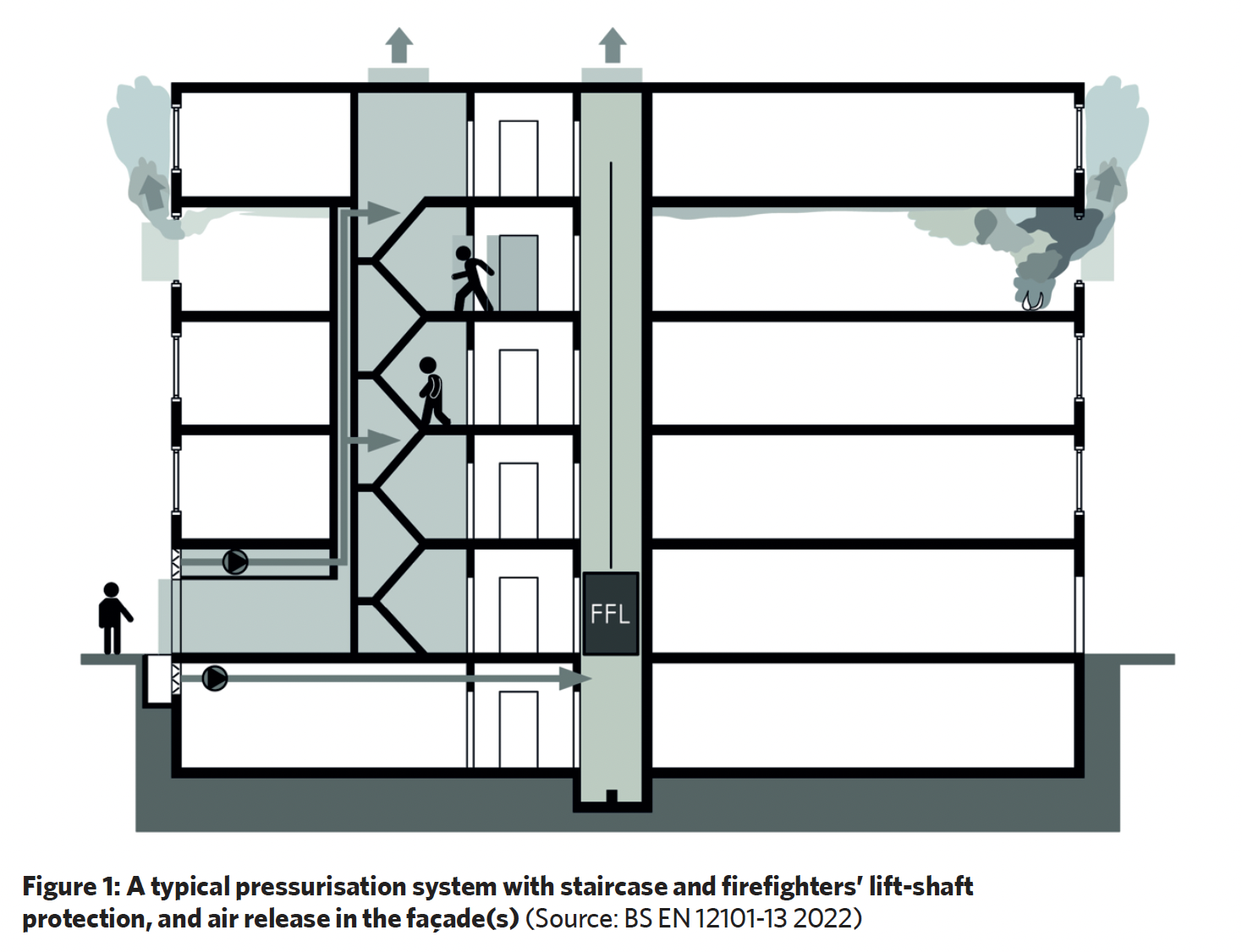
The PDS includes not only a means of supplying smoke-free outdoor air to the relevant protected areas to pressurise the spaces, but also the creation and maintenance of a safe route to release smoke and hot gases. This incorporates appropriate ducting, dampers and control (and, potentially, complete mechanical smoke and heat exhaust ventilation systems) to provide an assured smoke path from the unprotected, lower-pressure spaces and away from the building. This must be maintained while firefighting continues when, for example, fire compartment doors will be opened, and when building envelope changes are likely to occur, such as windows failing.
A key standard – BS EN 12101 Smoke and heat control systems – includes guidance and associated applications for the elements that should be employed to provide a building with robust systems that, in the event of a fire, allow occupants to escape safely, enable firefighting operations to progress, and offer protection to the property. This includes provisions and methods for: smoke barriers; natural and mechanical smoke and heat exhaust ventiators; fans; smoke ducts; smoke-control dampers; control systems; and power supplies.
The principal parts of standard BS-EN 12101 that specifically relate to PDS were published in 2022. BS EN 12101-13:2022 Smoke and heat control systems. Pressure differential systems (PDS). Design and calculation methods, installation, acceptance testing, routine testing and maintenance is a new part, replacing elements of the 2005 edition of BS EN 12101‑6, and includes guidelines for the design of PDS.
The fundamentals have not changed since the 2005 recommendations, in that it is still necessary to supply air to the protected space to create overpressure, and it is still necessary to vent off the air from the storey engulfed in fire. However, the standard now allows for the design of overpressure systems only, and systems based on underpressure have been removed.
Standard BS-EN 12101-6:2022 Smoke and heat control systems. Specification for pressure differential systems. Kits focuses on the devices used to construct pressure differential systems. It determines the components of ‘device kits’, how to divide them into families, and what tests should be carried out on individual kits. The goal of these tests is to prove that a given device kit can create the required level of overpressure and directional airflow from the space protected, with higher static air pressure than that of an unprotected adjacent space.
Ventilation systems designed in accordance with BS-EN 12101-13 should consist of components tested with reference to BS-EN 12101-6.
BS EN 12101-13 emphasises the need for a clear airflow path defined by the external air intake points, where the air flows inside a building, and where the air is being vented out of the building. While the previous guidance included similar requirements, these are now more precisely described, and extensive examples are provided. The PDS should be automatically triggered by the smoke-detection system on the outbreak of any fire (unless the detection is in the protected space and smoke has not yet been detected on a specific floor).
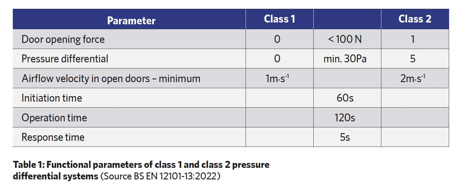
There are specific parameters set by the standard (as shown in Table 1) that should be designed, tested and confirmed for the installed PDS. In summary these are:
- Maximum door opening force – For normal use (in non-fire conditions) the maximum force at the door handle is 30N – when the PDS is operational that is allowed to be a maximum of 100N. This is for all floors, including the fire floor, and for each door within the escape route. The opening force is proportional to both the area of the door and the pressure differential, so larger doors require greater opening force.
- Minimum pressure differential – The previous requirement to maintain 10Pa within the staircases when an end door was open has been removed from the standard, significantly increasing the air streams required for the system. The standard introduces a 30Pa minimum overpressure level for all protected spaces, which includes both staircases and vestibules (if present).
- Minimum airflow velocity of 1m.s-1 (class 1) and 2m.s-1 (class 2) through the open doors between the protected spaces and the depressurised space to prevent smoke from entering the protected space. The supply air fan for the protected space must be able to supply sufficient airflow for all the relevant open-door areas.
- Maximum initiation time of 60 seconds between the activation of the PDS and when all necessary components are in the correct operating position (for example, damper vents) with the fan running.
- Maximum operation time of 120 seconds from the activation of the PDS to when the PDS is in its fully operational status.
- Maximum response time of five seconds in which the PDS shall achieve either the required pressure differential (including maximum door opening force) or the air velocity requirements through door openings.
The less-demanding class 1 will be applied in buildings with automatic water extinguishing systems employing quick response sprinklers, and for buildings lower than the height specified in the standard. In England and Wales, for example, this is up to 18m high, as the Building Safety Act defines a higher-risk building as 18m high or with at least seven storeys containing at least two residential units. (The higher-risk building definition is more precisely interpreted in the draft Higher-Risk Buildings Regulations 2023.2)
Class 1 is also applied in residential buildings if there are ‘at least two rooms without fire load between the protected space and the potential fire source and self-closing doors are present’.1 Class 2 applies in other circumstances or if it is demanded by the local regulatory authority.
The standard requires that air supply to the staircase or the lift/elevator shaft is established, as in the previous standard, to meet the greater of the pressure criterion and flow criterion. The new standard introduces the possibility of taking series flows into account when calculating leakage through lift doors into lift lobbies, which now makes it possible to reduce the effective leakage areas of the doors of new elevator shafts and, therefore, decrease the required airflow.
In a high-rise building, a significant challenge to pressure control is the stack effect, as it influences the pressure distribution inside the building, causing overpressure at the top and underpressure at the bottom in winter, and the opposite in summer.
The recent revision to the standard adds an additional requirement for buildings with a height of at least 60m – that additional pressure distribution analysis should be undertaken, for example, using numerical methods or computational fluid dynamics (CFD) at the design stage to account for more extreme factors that might influence the PDS performance, particularly those related to variations in wind direction and strength, and the stack effect.
A recent example of an application of a PDS was in Varso Tower in Warsaw, Poland, as shown in the photo of Figure 2 – a 53-storey skyscraper, 230m high to the roof (310m with its spire), that was completed in 2022 and is currently the tallest building in the European Union.
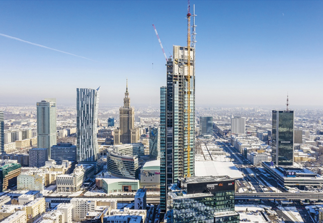
Figure 2: Varso Tower, Warsaw (Source: Exyte Hargreaves/SMAY)
Specifically selected fire dampers are installed in general ventilation systems as barriers, or in smoke exhaust systems to stop the spread of fire, heat and smoke, or to direct hot gases. Other dampers are used to allow the movement of air as part of the PDS and remove hot fire gases from the system. The smoke and heat control systems are used to generate and maintain positive pressure in protected spaces.
The objective is to maintain a directed, controlled airflow to the staircase zones by employing PDS to create a stable static pressure distribution in the whole staircase zone. This can be achieved by means of precise control, primarily by adjusting supply and exhaust airflow, and, secondly, by adjusting airflow resistance by actuating specific dampers to ensure that the air is routed correctly.
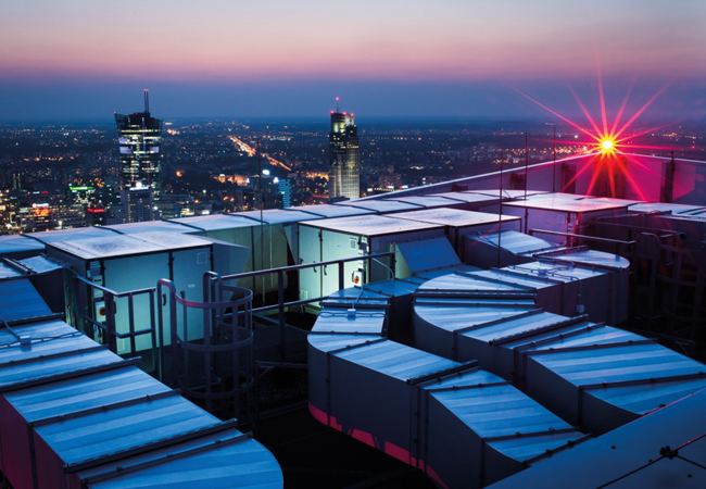
Varso Tower is protected with two reversible flow ventilation units on the opposite sides of the building at roof level (similar to that pictured in Figure 3) that, depending on the outside temperature and current pressure inside the protected space, will supply or extract air to maintain a stable static pressure distribution across the entire height of the building.
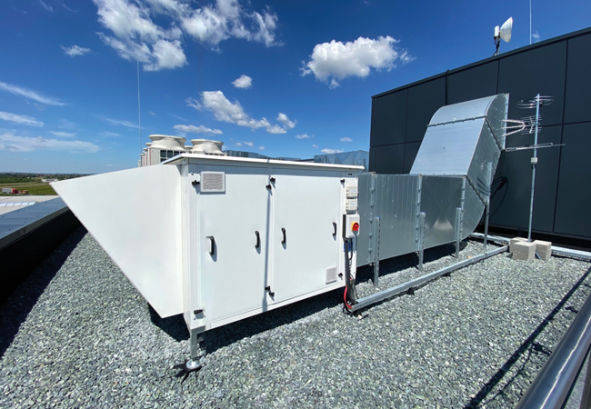
Figure 3: Example of roof-mounted reversible variable speed fan ventilation unit controlled as part of a PDS (Source: Exyte Hargreaves/SMAY)
All system components, such as controls and remote pressure sensors, are constantly monitored. The system moves from passive monitoring into active mode after receiving an appropriate signal from the fire alarm system. The regulation strategy is then to continuously measure and control the required static pressure difference between the multiple protected and reference zones, employing variable-speed fans with inverter control to supply the protected space with variable volume flowrates of air.
If the doors to a protected area, such as a stairwell, are closed, the system will be supplying a relatively small flow of air required to generate the required overpressure (typically in the order of 50Pa). When a door opens between the protected and unprotected zones, the system senses the drop in pressure and supplies an increased air volume flowrate to the protected zone, ensuring the appropriate airflow through the open door.
After the door is closed, the flowrate is reduced accordingly. The microprocessor-based control of the variable-speed fan ensures that the system can achieve more than 90% of the new air supply requirements within three seconds of a door being opened or closed, so meeting the requirements of BS-EN 12101-13.
A predictive algorithm, based on a neural network, prevents the risk of differential pressure oscillation even when conditions change frequently, such as during simultaneous evacuation of numerous spaces. Otherwise oscillation risks excessive pressures across escape route doors, so potentially impeding safe evacuation and firefighting. The controller is self-adaptive, automatically adjusting to alterations in air-leakage characteristics of the protected space and the air-release paths over time, so no manual recalibration is required.
Such a system is also resilient to the changing driving forces exerted by varying wind patterns, which dynamically affect the pressure distribution around, and in, the building. The system effectively remembers the settings for fan speeds and damper positions from previous operations, and uses this information so that it can respond more swiftly to future events.
The system components communicate over a low-voltage network loop (or ring) so that, in the case of one conductor being damaged, communication with all devices is maintained.
The systems in the Varso Tower self-test functionality every 24 hours, opening dampers and starting the fans at low speeds for a couple of seconds. The data collected during this test is stored, and status reports can be accessed or printed by the building operators.
This self-test ability reduces the opportunity for unexpected failure, enhancing the reliability of systems, and can contribute to statutory requirements for testing. BS EN 12101-13 considers that it is preferable that a PDS is self-monitoring and is ‘able to carry out regular functional tests on all operational components in accordance with the design and store this information automatically within the system’.
Working together with other passive and active fire-engineering measures, pressure differential systems can play an important role in building fire protection, including smoke control, maintaining escape routes, and improving access for firefighters. The concepts of the PDS are relatively straightforward; however, developments in fan construction and regulation, as well as sensing and control techniques – coinciding with heightened awareness of the hazards of fire in higher-risk buildings – has increased the opportunity to implement PDS as part of an integrated building safety system.