The supply and removal of air by ventilation terminals significantly impacts the effectiveness of the environmental system. In occupied buildings, this can influence comfort, productivity, and occupant wellbeing, as well as the environmental impact and financial cost of operation. This CPD will focus on some of the basic parameters that describe air movement associated with provision of ventilation for occupied spaces.
The start of any ventilation system design will be an examination of the room-by-room loads and outdoor air requirements, with checks and iterations to moderate those needs by refining the building structure, fenestration and shading – as well as expectations of occupancy and use. The iterative process depends on system constraints and needs that are influenced by numerous factors. These could typically include: the building and room types; planned usage; spatial restrictions; aesthetic demands; matching of any existing systems; client expectation; capital budgets; and designer preferences.
Finally, when the system type has been selected, the supply and extract terminals, known collectively as ‘air terminal devices’ (ATDs), may be evaluated and selected – a process that, in itself, may demand a reconsideration of earlier decisions. As noted in the BSRIA BG 101 guide, the choice of system, and associated supply and extract position (for example, high-level diffusers, mid-level or low-level displacement terminals) may well be dictated by the room loads, the configuration of the space, and the use of the space.
The goal is to achieve good ventilation effectiveness – that is, the ability to remove internally produced contaminants, avoid draughts, and ensure that the air is at a satisfactory condition to contribute to appropriate occupant comfort. Aside from the ability to ventilate the space, there are other important factors that will influence ATD selection, which would include: aesthetics; cost; space requirement; acoustic performance; energy efficiency; maintainability; and sustainability.
For most applications, it is beneficial to define an occupied zone – typically, a volume where thermal comfort conditions are maintained for occupants, bounded by zones parallel to walls, ceiling and floor, as illustrated in Figure 1.
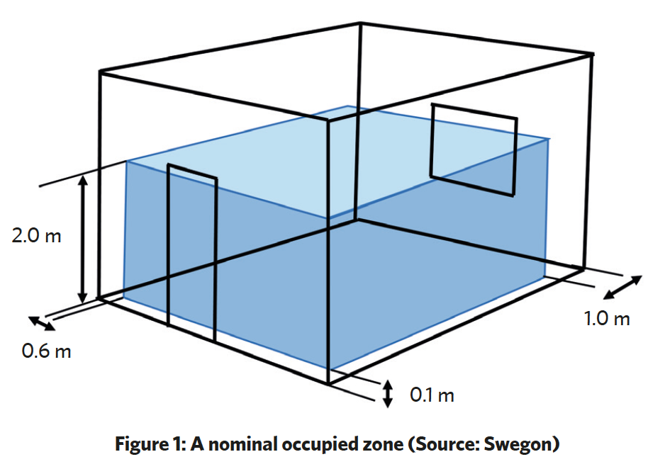
The selected room volume will be related to the expected use of the space. It is rare that people sit directly next to walls, and there are very few occupants who reach beyond two metres high. For situations where shoes and leg coverings are de rigueur, 0.1m from the floor may be seen as a reasonable boundary. However, where there are likely to be exposed ankles, care is needed to avoid draughts when introducing cool air. (The concept of an occupied zone is not as relevant with a displacement ventilation system.)
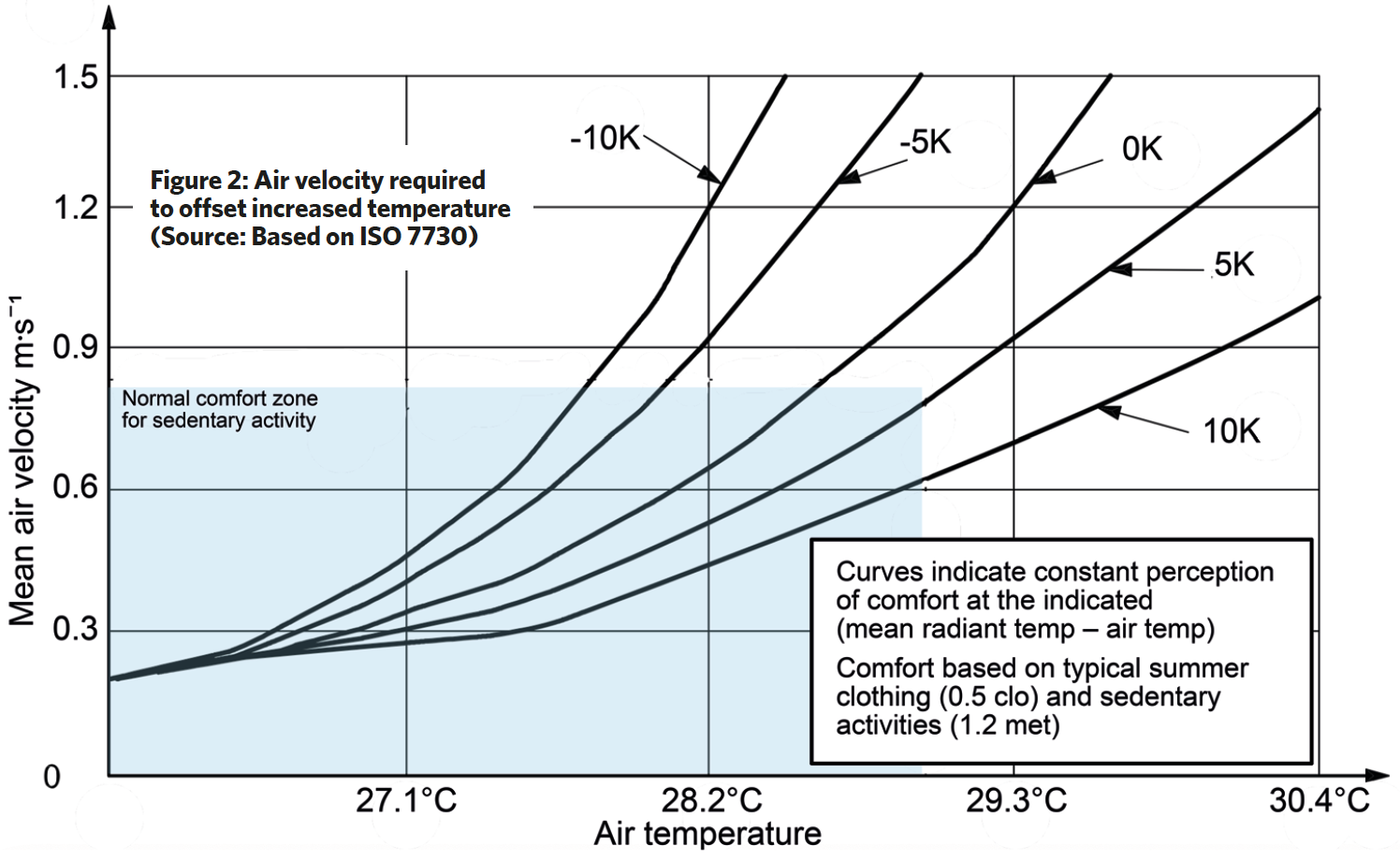
Normally, the air velocity in the occupied zone would be designed in the range 0.15m.s-1 to 0.25m.s-1. Below 0.05m.s-1 the air is considered ‘stagnant’ and not appropriate for sedentary occupation. However, as with so many ‘rules’ in building services engineering, it is important to consider the potential benefits of stretching these limits.
For example, in cooling applications as illustrated in the chart in Figure 2, based on ISO7730,2 where the curves indicate a constant level of comfort (for office-type applications) a higher air velocity may be used to offset the warmth sensation caused by increased temperature – so reducing the potential cooling requirement. This will be significantly affected by the mean radiant temperature, qr – when qr is relatively low (the higher curves), a larger increase in air velocity is needed to maintain comfort as air temperatures rise.
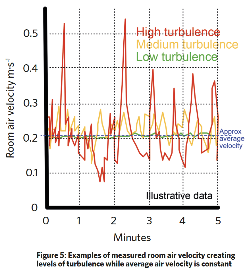
Fluctuations in air velocity will impact occupant comfort, and for cooling applications may be assessed by determining the turbulence intensity (Tu). As Tu increases, the acceptable mean air velocity for comfort will reduce. For air conditioned and mechanically ventilated buildings, the draught rating (DR) combines air velocity, temperature and turbulence intensity into a discomfort factor that is often used in conjunction with predicted percentage of dissatisfied (PPD) to provide an assessment of comfort conditions in a space. A DR value of approximately 15% is typically considered acceptable for people undertaking light, mainly sedentary activity (with any draught being assumed at neck level).
The significance of perturbations in air velocity (that is, air speed and direction) can potentially transform a comfort zone into one that generates occupant complaints. For example, as taken from CIBSE Guide A,3 if the temperature of air passing over the body is 23°C and the turbulence intensity is 60%, a draught rating of 15% corresponds to an air velocity of 0.14m·s–1. However, if the turbulence intensity is only 10%, the limiting velocity for comfort is increased to 0.23m·s–1.
For comfort, it is recommended3 that there should be not more than 3K difference in air temperature between ankles and head. However, if air velocities are higher at floor level than across the upper part of the body, CIBSE recommends that this could be increased to a maximum temperature gradient of 2K for each metre height.
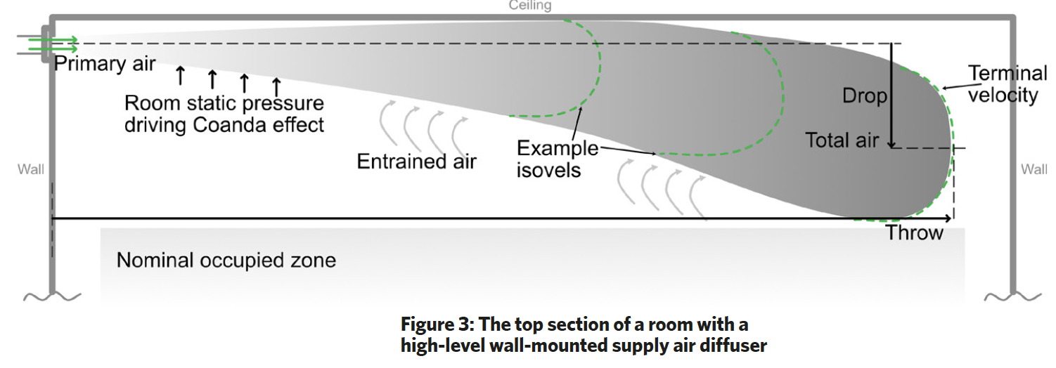
To characterise the moving plume of air emanating from a supply ATD, as illustrated in the high-level example of Figure 3, there are several terms that are reasonably universal in application, although quoted ‘typical’ values can vary between manufacturers. (BS EN 127924 provides an extensive list of standard terminology.)
The primary air leaves a supply ATD at an outlet velocity, m·s–1, which will be determined by the total pressure (velocity pressure + static pressure) at the rear face of the ATD and the geometry of the outlet. The velocity of the air in the room is often described by considering envelopes known as an isovels (as in Figure 3) that indicate a boundary line linking points of common air velocity.
As air leaves an ATD, room air is entrained and mixed into the air stream, so reducing the velocity of the moving mass of air while increasing the total volume. After the air leaves from the ATD the flow tends to drop or rise depending on its temperature relative to the room air. As the velocity and inertia of the total air reduces, its trajectory will become increasingly influenced by gravitational forces. In a horizontal supply, the air stream will tend to curve upwards if the incoming air is warmer than room air and downwards if cooler. The velocity of the air will reduce more swiftly if the air has a greater spread as it is introduced into the space, and the air will increasingly diverge (typically with5 an included angle of between 20-24°) as it entrains surrounding air, so increasing the total air volume.
The terminal velocity is when it is assumed that the inertia has reduced to such a point that gravitational forces begin to dominate, typical considered as 0.25m.s-1 although, as reported by Legg,6 this can be a rather arbitrary value. It is variously referenced between between 0.25m.s-1 to 0.75m.s-1. The distance measured from the face of the ATD to that point, in the intended direction of flow, is known as the throw, measured in metres. Values of throw, flowrates, outlet velocity, distribution characteristics, and noise data are provided in manufacturers’ catalogue data for ranges of ATDs – they will all vary depending on the chosen primary flowrate.
In some situations, a short throw length is required – for example, to prevent the total air stream striking a structural beam or light fitting, so producing an unwanted deflection of high-velocity air into the occupied zone (Jones5 provides a useful commentary on the influence of obstructions on supply airflow to allow more nuanced selection of supply ATDs).
A long throw can usefully provide increased opportunity to entrain room air as well as supplying treated air across a greater area. Overblow describes an airstream that meets an opposing wall and is deflected downward towards the occupied zone, as part of the throw distance. Supply air diffusers that discharge towards each other may cause a downward airstream that can create draught in the occupied zone. However, with proper consideration of throw, the outlets can usually be placed relatively close to each other without the combined stream reaching the occupied zone at a velocity beyond the comfort range.
If the supply air is introduced adjacent and parallel to a surface, as is often the case from a diffuser mounted less than about 300mm from a ceiling, the ‘Coanda effect’ (or ‘ceiling effect’) will tend to extend the air’s throw as the airstream is pressed to the surface by the higher room static pressure. An ATD design that strengthens the Coanda effect can deliver increased cooling effect to the room, with a lower risk of draught. As discussed in CIBSE Journal,7 exposed, suspended supply diffusers without an adjacent ceiling may be augmented with a horizontal, surrounding ‘Coanda plate’ that has been shown to increase the effective throw.
Practically, the selection of ATDs can readily be undertaken by employing one of the many manufacturers’ ATD selection programmes or by employing CFD simulation tools, but can also be simply verified with sketched Straub8-style diagrams that are similar to that shown in Figure 3.
Selection will include considerations of the design air volume flowrate, distance available for throw, spatial constraints, and aesthetic demands. The selection and location of extract ATDs is typically less critical than supply, since flow through an exhaust ATD has very little influence on the local air movement, as air approaches from many directions so that significant velocities only occur close to the device.
However, as discussed in the September 2022 issue of CIBSE Journal,9 their position can have a significant impact on the containment of contaminants emitted in the space – they should not encourage entrainment of contaminant across occupied zones but can usefully be located close to points of contaminant generation. Generally, it is beneficial if air is extracted near points of heat gain in cooling applications, and vice versa where heating is the dominant mode.
To avoid short-circuiting primary air directly into extracted air, ATDs are preferably located outside the throw of the supply (and potentially in what would otherwise be a stagnant zone). For displacement ventilation systems, extracts would be at the highest level in order to extract the warmest air.
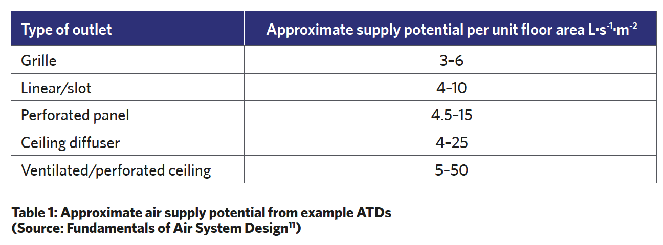
The types of ATDs are many and various. The freely downloadable HEVAC guide to air distribution10 provides an extensive illustrated description of the most common type ATD types. The flows available from supply ATDs would be determined from manufacturers’ data. However, Table 1 provides an indication of the comparative ability of ATDs to effectively move air into a space.
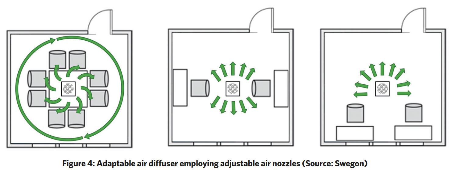
Adjustable devices offer flexibility of application that can be utilised at the time of system commissioning (or recommissioning) to service flexible use of spaces. For example, the ceiling diffuser application in Figure 4 employs air nozzles that can be adjusted so that the distribution pattern suits the room. The standard setting would typically be a swirl pattern that can supply the air volume across the whole room. However, it is also possible to adjust the distribution pattern so that, for example, the airflow is directed away from workstations, to minimise the risk of draughts.
No matter what overall system is employed in the building – whether it be mixing, displacement or laminar flow – ATDs will ultimately determine the success, or failure, of the whole installation. And so, as with all building services systems, supply and extract devices merit the care in their selection and application that reflects their critical role in providing good quality built environments.
Assessing turbulence and draught
The turbulence intensity (Tu) is the ratio of the root mean square of the fluctuating air velocity to the mean air velocity expressed as a percentage (40% is a regularly used default value). Figure 5 illustrates different levels of turbulence for a room where the average velocity is the same, but the method of air supply has been varied (for example, different diffusers or obstructed flow), so producing different levels of turbulence.
The draught rate (DR) is the percentage of people predicted to be bothered by draught and can be quantified2 by DR = ([34 – qa] [ – 0.05]0.62) (0.37 . .Tu + 3.14)%
Where DR = predicted percentage of people dissatisfied due to draught, %, qa = local air temperature, °C, = local average air velocity, m.s-1. This may be applied where 20°C < qa < 26°C and 0.05m.s-1 < < 0.5m.s-1 and 10% <Tu < 60%
Tim Dwyer, 2022
References:
- BSRIA BG 30/2007 Guide to HVAC Building Services Calculations, BSRIA/CIBSE 2007.
- BS EN ISO 7730:2005 Ergonomics of the thermal environment Analytical determination and interpretation of thermal comfort using calculation of the PMV and PPD indices and local thermal comfort criteria, BSI 2005.
- CIBSE Guide A 2015 Environmental criteria for designs
- BS EN 12792:2003 Ventilation for buildings – Symbols, terminology and graphical symbols, BSI 2003.
- Jones, WP, Air Conditioning Applications, Routledge; 2nd edition, 1996.
- Legg, RC, Air conditioning systems – Design, commissioning and maintenance, Colby Press 2013.
- Jones, R, Heightened awareness, CIBSE Journal May 2019.
- Straub, HE et al, Distribution of Air Within a Room for Year-Round Air Conditioning – Part I, University of Illinois Engineering Experiment Station Bulletin 435, 1956.
- Dwyer, T, Targeting the breathing zone, CIBSE Journal September 2022.
- Guide to Air Distribution Technology for the Internal Environment, Issue 2 HEVAC 2015.
- Bean, R, Fundamentals of Air System Design – Self learning coursebook, ASHRAE 2010.