![]()
Traditionally, buildings in temperate climates, such as the UK and much of Europe, have used natural means of providing outdoor ‘fresh’ air to occupied spaces.
However, despite the progress in passive ventilation systems, mechanical ventilation is likely to be required in larger, and possibly urban, residential, commercial and industrial applications in order to overcome challenges such as deep and obstructed floor plans, high occupant density, internal equipment loads and emissions, and poor outdoor air quality.
There are good reasons to ensure that the volume flow and distribution method for the air are optimised to suit the application, not least to minimise operational expense, but also to reduce environmental impacts.
When assessing the mechanical ventilation requirements for occupied buildings, the key criteria are health, safety, wellbeing, specific application requirements (such as air humidity) and care of the building structure. These will, in turn, impact the performance of building occupants, the energy consumption in the building, and the building economy in general.
As with any system development, it is important that the problem is properly defined before attempting to work towards a solution, with each application and subsequent installation benefiting from individual assessment. That is not to infer that every mechanical ventilation design is unique in concept and function, but for effective and efficient building operation, the solution must be led by the specific needs of the application.
To determine whether natural ventilation, mechanical ventilation (with/without cooling/heating/humidification) or a hybrid (air-water or air-refrigerant) system is likely to be most suitable requires an initial assessment of: the building shape, structure, occupants and surroundings; the heating and cooling loads; and the particular environmental control needs. CIBSE Applications Manual AM10 Natural ventilation in non-domestic buildings (Figure 2.8) provides a useful flowchart to assist in this process.
The system selection process is iterative, and it is only through considering the detailed requirements of the individual spaces in conjunction with building-level aspects that an overall system concept will emerge.
If, as a result of an initial analysis, a mechanical ventilation system is required – which might be part of a hybrid system – then an outline ventilation system design process ensues, which might usefully follow the path suggested in the outline of the ventilation design process (Figure 2.1) from CIBSE Guide B2,1 which goes from identifying the requirements through to completing the calculations, drawings, schedules, and specifications.
To develop a system that delivers appropriate ventilation in the individual rooms will require a room-by-room analysis. The creation of ‘room data sheets’ or equivalent will identify the design parameters that are required for each space.
If natural ventilation is not feasible, suitable or sufficient, a mechanical supply of outdoor air will be needed for ventilation purposes. Outdoor air may provide the total airflow (in a ‘full fresh air’ system), but is more likely to be a fraction of the total airflow.
The total maximum amount of air that will be needed by the room as a mass flow, m kg.s-1, will typically be determined from the larger of the ventilation air requirement or the design (maximum) room sensible cooling load, qs kW. To determine the load-based flowrate, the room-supply air temperature differential, ∆θ = θr – θs K, will be needed. This will be intrinsically linked with the system type and so may present an iterative stage in the early design process.
MOVING ENERGY AROUND A BUILDING
To determine the mass flow rate, m kg. s-1, of a heating/cooling fluid to provide a load of qs kW qs = m Cp ∆θ where Cp (kJ. kg-1. K-1) is the specific heat capacity for the fluid.
The fluid volume flow, m3. s-1 is given by m/ρ where ρ kg. m-3 is fluid density.
Comparing using water and air to move 1kW cooling to the room.
For air with ρ = 1.2kg. m-3; Cp = 1.02kJ. kg-1. K-1 with a nominal ∆θ (room – air supply) of 10K, air mass flowrate = 1kW/1.02 x 10 = 0.0980kg. s-1 and volume flowrate ≈ (0.0980/1.2)m3. s-1 = 0.0817m3. s-1
For water ρ = 1,000kg. m-3; Cp = 4.2kJ. kg-1. K-1 with a nominal ∆θ (water return – flow) of 8K water mass flowrate = 1kW/4.2 x 8 = 0.0298kg. s-1 and as a volume flowrate ≈ (0.0298/1000) m3. s-1 = 0.00003m3. s-1
Pump or fan power (W) to move water or air through a pipe or duct = volume flow (m3. s-1) x pressure drop (Pa)
Considering 1m pipe (with nominal pressure drop of 100Pa. m-1) or duct (with nominal pressure drop of 1Pa. m-1)
Air power = 0.082m3. s-1 x (1m x 1 Pa. m-1) = 0.082W for each kW for each 1m duct
Water power = 0.00003m3. s-1 x (1m x 100 Pa. m-1) = 0.003W for each kW for each 1m pipe
Often, hybrid systems are considered that can provide tempered (and possibly humidity-controlled) air to satisfy the ventilation requirement and, additionally, employ integrated or separate cooling and/or heating elements, which use water or a volatile refrigerant, to meet the remainder of the room load. For buildings with several environment-controlled rooms, there can be significant benefits in using hybrid systems that may include reduced services distribution space, improved controllability, and reduced operational costs.
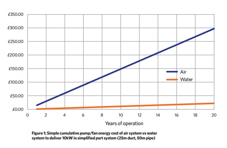
Water- and refrigerant-based distribution systems are well placed to maximise opportunities from applying heat pump ‘heat recovery’, as well as benefiting from significantly smaller conduits and reduced distribution power compared with air systems to provide cooling and heating (see boxout, ‘Moving energy around a building’). Taking an example of a 10kW cooling load supplied through a 25m duct compared with a 50m (flow and return) pipe, with a conservative electricity price of £0.35 per kWh, over an eight-hour working day, five days a week, over 52 weeks a year, and assuming that the efficiency of the pump/fan is 70%, would provide a simple comparative pump/fan energy cost, as illustrated in Figure 1.
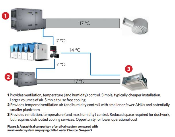
In this greatly simplified example, the cost to distribute waterborne energy is less than 7% compared with using air. This excludes any allowance for fittings, controls and terminal devices – these must be considered in any complete analysis. In terms of systems, this could lead to the air-water arrangement illustrated in the lower part of Figure 2 that can be compared with the all-air system shown above it.
The all-air system may be more appropriate for spaces with large ventilation loads, such as conference rooms, whereas the lower air-water system may be more appropriate, for example, in a modular office or hotel room. In this hybrid system, the air handling unit (AHU) and ducts are sized to meet the maximum ventilation requirement, while the main cooling (and heating) is managed in a piped water system.
A significant benefit of the air-water system is that there are smaller/fewer AHUs, as well as the ducts being smaller. Additionally, the chilled water to the room units will normally be distributed at a higher temperature than the temperature required to cool the air in the AHU, which can provide savings in cooling costs. However, the lower air flowrate through the ducted system will reduce the opportunity for employing air-based ‘free cooling’.
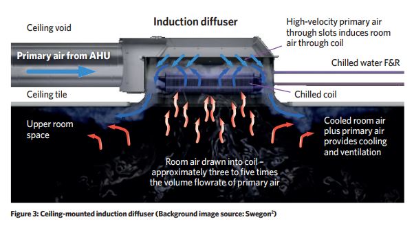
The room unit may be one of several types – such as fan coil, active chilled beam, passive chilled beam, chilled ceiling panel, or the relatively recent reinvention of an induction unit incorporated into a ceiling diffuser, as illustrated in Figure 3. Such new-style induction units operate at a lower pressure compared with the noisier old-type induction units, with the supply air creating a low static pressure zone, so drawing room air across the water coil, to mix with the ducted supply air that is then delivered into the room.
For each volume of ducted ventilation supply air (that would be tempered and potentially humidity controlled) the induction diffuser will deliver that volume of air mixed with the induced recirculated room air. This provides the efficiencies of an air-water system without the additional hardware of a fan coil or the bulk of a chilled beam, while ensuring good mixing with the room air and no risk of draughts from cold treated air.
The proportion of recirculated room air drawn through the heat exchanger is typically about three to five times the proportion of primary air – so, for example, if 20L.s-1 supply air comes from the air handling unit, then approximately 60-100L.s-1 room air will pass through the exchanger and be tempered. Whichever mode and type of environmental system is employed in intermittently occupied spaces, there can be significant operational benefit in employing demand-controlled ventilation (DCV). This adapts the flowrate of the ventilation air to satisfy the number of occupants.
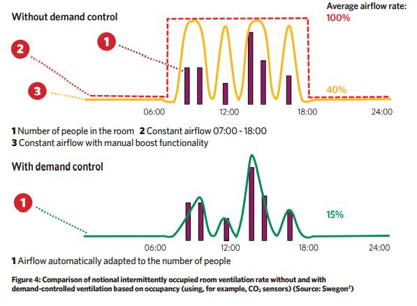
As illustrated in Figure 4, an example room with variable occupancy could be ventilated with a constant volume flowrate system, which would deliver the volume flow indicated by the red dotted line, so providing a reference average for comparison of 100% full flow. This system is often improved by an intermittent boost facility (such as one that could potentially be manually activated by a café owner when it is noticed that the number of customers increases); this can provide a significant reduction in flowrate, as indicated by the yellow line and equating, in this example, to an average flowrate of 30% full flow.
Where even closer control is required (for example, to meet low energy, green or healthy building certifications), a fully automatic DCV system may be employed, potentially actuated with feedback from CO2 sensors (to detect occupancy) or VOC sensors (that can detect occupants by proxy, as well as other pollutants); this particular example would show an average supply ventilation air flowrate of approximately 15% full flow.
The same concept might be applied where there is a varying casual source of contaminant that is possible to sense in real time, such as cooking processes, copying/printing machines, or other emissions, such as from painting, gluing, 3D printing and surface preparation (for example, sanding). To use DCV means reduced airflow, which, in turn, means lower energy consumption for the fans, and a reduced need for adding heating/cooling. It is usually also possible to reduce the size of the indoor climate system as a whole (from AHU to ductwork), saving space, embodied carbon and investment costs. (For further discussion and application of DCV, see CIBSE Journal June 2019, CPD Module 148 ‘Demand-controlled ventilation for comfort, wellbeing and resource efficiency’.)
Defining the key areas and divergently exploring the problem are just the first steps in developing a suitable ventilation system for a specific application – a future CPD will build on the considerations covered in this article to explore room air distribution and system types.
© Tim Dwyer 2022.