There is an inexorable move towards the application of heat pumps, both in the refurbishment of buildings and in new-build projects. This is by no means a universally simple move, particularly where applications might be considered as being outside the effective ranges of widely available heat pumps and, in almost all installations, a bespoke solution will be required.
This CPD will consider the basic factors that impact the performance of
air-to-water heat pumps, and provide some examples of combining heat pumps with other heat sources in larger residential and commercial applications that can be successfully applied to legacy systems to meet building heating demands more effectively.
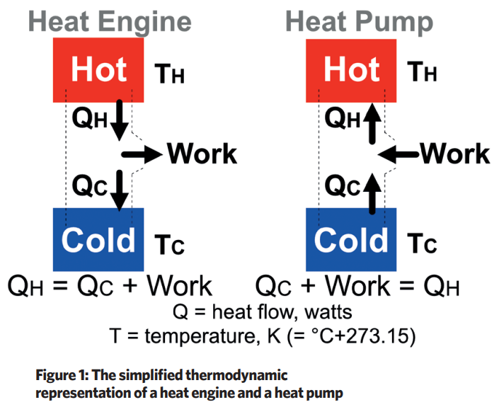
There is practically a limitless source of heat available globally, from the air, water courses, and the ground. The heat pump draws on this massive resource by applying the thermal processes of a ‘reverse’ heat engine. The classical heat engine, illustrated in Figure 1 (overleaf), uses energy provided in the form of a higher temperature heat source to deliver work, and then exhausts low temperature heat that has not been utilised to deliver work.
To ‘reverse’ the process of a heat engine, a vapour compression heat pump will apply external work to extract lower grade heat QC from a lower temperature source and delivers heat QH to a higher temperature output by means of a circulating working fluid, the refrigerant. The work of a compressor will increase the pressure and the temperature of a working fluid by moving (or ‘pumping’) low temperature heat to a higher temperature output.
The performance of heat pumps (to deliver QH) is usually characterised by a coefficient of performance (COP) – the number of units of heat delivered per unit work input. A heat pump is subject to the thermodynamic limitations of the heat engine and so the maximum theoretical efficiency (the Carnot efficiency) can be identified from the ratio of absolute temperatures (in K)TH/(TH-TC).
In real systems that are subject to inefficiencies, such as friction and radiative heat losses, the achievable COP will likely be under half of this theoretical value. However, the COPCarnot is useful as it can be used to interpret the pro rata impact of varying the relative hot and cold temperatures on the operation of heat pumps. Hence, to operate at a high COP, the heat delivery temperature TH should be as low as possible and the source temperature TC as high as possible.
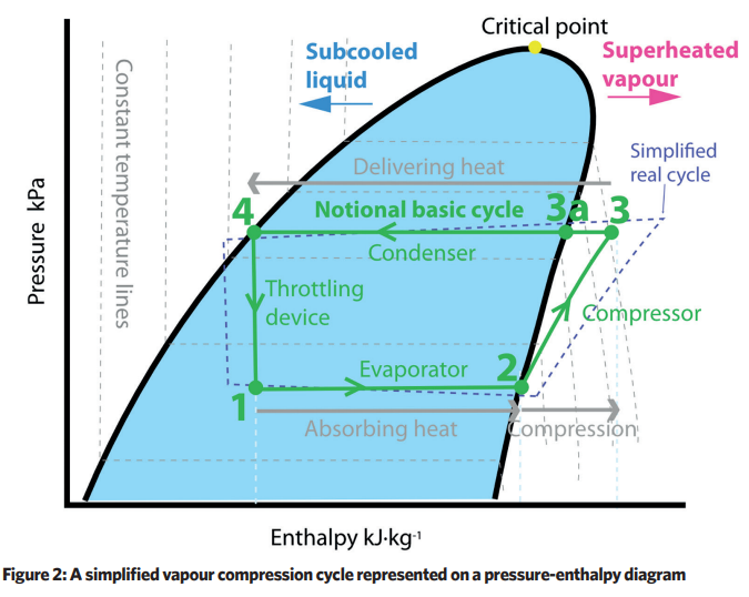
The heat pump cycle may usefully be illustrated using a pressure-enthalpy diagram, as shown in Figure 2 (overleaf). The heat pump system draws in lower temperature heat (for example, from outdoor cool air) at the evaporator (1→2), as the low pressure working fluid (the refrigerant) changes state (evaporates) into a low temperature gas.
The compressor (normally electrically powered) adds work, increasing the pressure and temperature of the refrigerant gas (2→3). The condenser then releases heat to a cooler surrounding fluid (for example, the building’s heating medium – typically water) as the superheated gas initially drops in temperature (3→3a) and then condenses (3a→4). Practically, for effective operation of the heat pump, this condenser process typically limits the temperature difference in the heating medium flow and return to around 5K.
Finally, the cycle completes as the refrigerant passes through a throttling (or expansion) device (a small orifice) to lower the pressure and temperature of the fluid so creating a cool liquid vapour mix at entry to the evaporator (4→1). (The dotted blue cycle in Figure 2 provides an interpretation of how a real cycle will compare with the theoretical one.)
The temperature and pressure of the evaporator and condenser will be determined by temperatures of the heat source and the heating medium that is receiving the heat. As these temperatures diverge, and so the temperature ‘lift’ increases, the heat pump COP and heat output reduces.
If the heat pump is adequately sized, the heat output of the condenser can be controlled by varying the flowrate of refrigerant around the system, either with an on-off, or variable speed compressor.
Typically, the application of air-to-water heat pumps to supply heat for a building will demand the most heat when the outdoor temperatures are low so the temperature lift is highest and COP lowest. The available output from the heat pump will reduce as the outdoor temperature drops. Additionally, as the outdoor air temperature reduces, ice can accumulate on the evaporator if the coil surface temperature drops below 0°C.
Water vapour in the air condenses and freezes on the coil surface – this is likely to occur as the outdoor temperature drops below about 6°C and is exacerbated by outdoor air that is more humid. Frosting can reduce the COP by between 15% and 20%1 and reduce the heating capacity by 40%,2 not only because of the insulating effect of the ice, but also as a result of the mechanisms needed to remove the ice.
As the ice accumulates, heat pump controls will typically sense the change – based on measuring such variables as COP, heat output or air flowrate – to determine when the coil requires de-icing; practically, this is likely to be when the air path through the coil is obscured by approximately 50%. Depending on the manufacturer, de-icing is likely to be provided by one of three different methods.
The most common, speediest, and most efficient is to reverse the cycle so that hot gas from the compressor is passed into the evaporator (by way of a reversing valve), so melting the ice. The other two methods are easier and cheaper to implement: the first is to use an electric heater directly on the coil to melt the ice, though this can be costly to operate; and the second is very simple, with the system turning off to let the ice melt – but this is likely to take some time to de-ice the coil.
During defrost, the heat pump will not be delivering any heating to the load (and the evaporator fan will be off). Once the unit is free of frost the unit will resume the heating cycle. An effective defrost solution is likely to operate no more than twice an hour and is likely to last in the order of 10 minutes. Some coils have coatings to reduce the potential for icing, and others that employ profiled finned coils – aimed at improving heat transfer – can be more adversely affected by frost accumulation.
Clearly, the output of an air-to-water heat pump will fluctuate significantly not only because of the manufacturer’s design but also in relation to outside air temperature (and humidity) and the temperature at which the heat is delivered to the internal load.
Methods of determining representative COPs, to more reliably model and compare different systems, are evolving and, most recently, have been drawn together in BS EN 15316-4-2 as discussed in the useful article in the REHVA Journal by Johann Zirngibl.2 BS EN 14511-2 20183 provides a set of testing conditions for evaluating the performance of heat pumps at a range of outdoor conditions and delivered temperatures, in an attempt to provide a representative range of operating performance.
Manufacturers should be able to provide, at least, the BS EN 14511 values – which relate to ‘integrated capacity’ that accounts for defrost cycles (as opposed to ‘gross’ capacity). The methodology of BS EN 14511 can be used to produce a more detailed, hour by hour, model of performance data that is contextualised to the location and application.
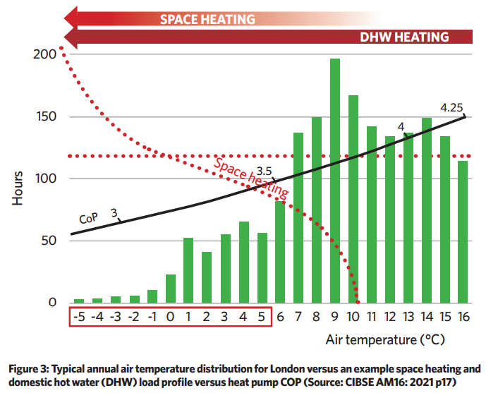
Figure 3 provides a simplified summary of the COP of a typical air-to-water heat pump for a London location, related to banded hours of external dry bulb temperature, to meet the heating and domestic hot water (DHW) loads.
As suggested by CIBSE AM16,1 ‘where COPs can be provided (by the manufacturer) across a range of ambient temperatures and part-load conditions, this data can be used in combination with the building load profile and local weather data to gain an accurate understanding of heat pump efficiency for a given application in any external ambient condition’.
A buffer vessel is often employed to provide system stability and enable more effective operation of the heat pump (as illustrated in Figure 4). Although smaller than a typical ‘thermal store’, one of the buffer’s primary roles is to provide a store of heated secondary water to reduce the on-off cycling of heat pumps, as it is desirable that compressors cycle no more than three times an hour.
The buffer also provides a modest store of heat that during defrost allows the system to continue circulating heated water. (Thermal stores also may be usefully employed on the load side of systems supplied from heat pumps, as discussed in CIBSE CP14 and CIBSE AM16.)
Air-to-water heat pumps may be deliberately undersized, particularly where an existing fossil-fuelled heat source is being retained or there is little or no fabric improvement in a building refurbishment, or where there is little opportunity for increased heating distribution flowrates or greater heat transfer capabilities.
It may simply be a design decision that lower capital cost, possibly reduced system embodied carbon, or space constraints makes the case for more than one heat source in what is known as a polyvalent system. An auxiliary heat source could be used for times when loads are uncommonly high or when the COP, and output, of the heat pump reduces at lower outdoor temperatures, or the load increases significantly. In any case, as noted in CIBSE AM16, an air-to-water heat pump that is sized for peak load, at a rarely occurring design heating temperature, will result in a unit that is oversized for the majority of its operational life.
The complementary heat might be provided by, for example, an electrical heating element in a buffer vessel, or an associated gas, oil or electrical boiler, or an alternative renewable source. The heat pump may well have the facility to control operation of the auxiliary heat source so that they work most effectively as a pair. A system with two such sources of heat is known as a bivalent system (as opposed to the monovalent single heat source system).
The simplest format is where heat pumps are equipped with a direct electric heating element as backup for unusually cold weather, or possibly as a boost to heat DHW – these are sometimes referred to as monoenergetic systems, as the same heat source, electricity, is used for both. These are particularly suitable for flow temperatures up to heat pump maximum flow temperature and for applications where DHW may be generated by other means.
There are a number of bivalent arrangements that may be adopted. The example system in Figure 4 illustrates a second heat source (in this case, a boiler) operating in parallel with the heat pump.
The control regime may be set to allow concurrent parallel operation or, potentially, in a ‘switch’ mode boiler-only operation, and can maintain a higher system flow temperature than would be available from the heat pump alone, or alternatively to deliver a variable flow with a constant temperature matching the heat pump output.
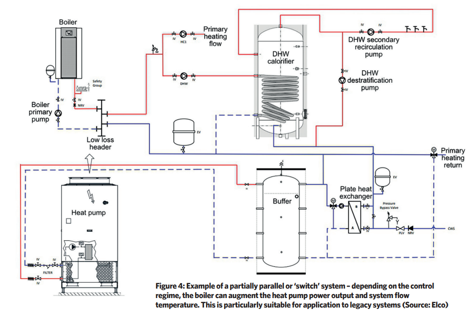
Such a system can be successfully applied for legacy building heating systems with externally compensated flow temperatures with peak design flow temperatures of, for example, 82°C. In winter, when the return temperature is too high to return to the heat pump, the three-way valve on the primary heating return directs all the flow to the boiler header.
However, when building heating loads are lower and flow compensation has reduced the flow temperature, the return passes into the heat pump buffer, as the heat pump can make a contribution up to around 60°C. In either case, significant DHW preheating is always available from the heat pump (via the plate heat exchanger).
Since the coldest external temperatures occur for a relatively small number of hours (as shown in Figure 3), heat pumps employing variable speed compressors in such an arrangement as illustrated in Figure 4 are often able to meet the majority of the annual heating load, with the boiler operating for very few hours per year.
Precise assessment of the optimum system arrangement is challenging, particularly in these times of volatile energy supply markets. However, any design must be based on a holistic and individual assessment of the demands of a particular application. This may employ simulation modelling, banded weather data or, potentially, heating degree days, that can then be used to determine the optimum energy – and environmental – solution for a specific application.
© Tim Dwyer 2022